CONTROLS, INDICATORS AND COMPONENTS
Page
14
Copyright Trace Engineering Company, Inc.
5916 - 195th Street N.E.
Arlington, WA 98223
Telephone: 360/435-8826
Fax: 360/435-2229
www.traceengineering.com
PS Series Inverter/Charger
Part No. 3597
Rev. D: November 23, 1999
GEN - RJ11 connection jack for the optional plug-in Generator Relay Module. The Generator Relay
Module consists of signal relays and allows connection and automatic control of “two-wire” type
generators. The relays are single pole double throw, five amp relays. Both the normally closed and
normally open contacts are available for each relay. The operation of each relay is controlled and
adjustable with a SWRC via the user menu.
RC8 - RJ11 connection jack for the optional plug-in RC8 remote. Allows remote On/Off control of the
inverter at a distance of up to 50 (RC8/50) or 100 (RC8/100) feet away, functionally identical to the On/Off
Power Switch on the inverter.
BTS - RJ11 connection jack for the plug-in external Battery Temperature Sensor (BTS). The BTS
automatically fine-tunes the charging process of the battery charger in relation to temperature. If the
temperature sensor is NOT installed and if the battery is subjected to large temperature variations, a
shorter battery life cycle may be expected.
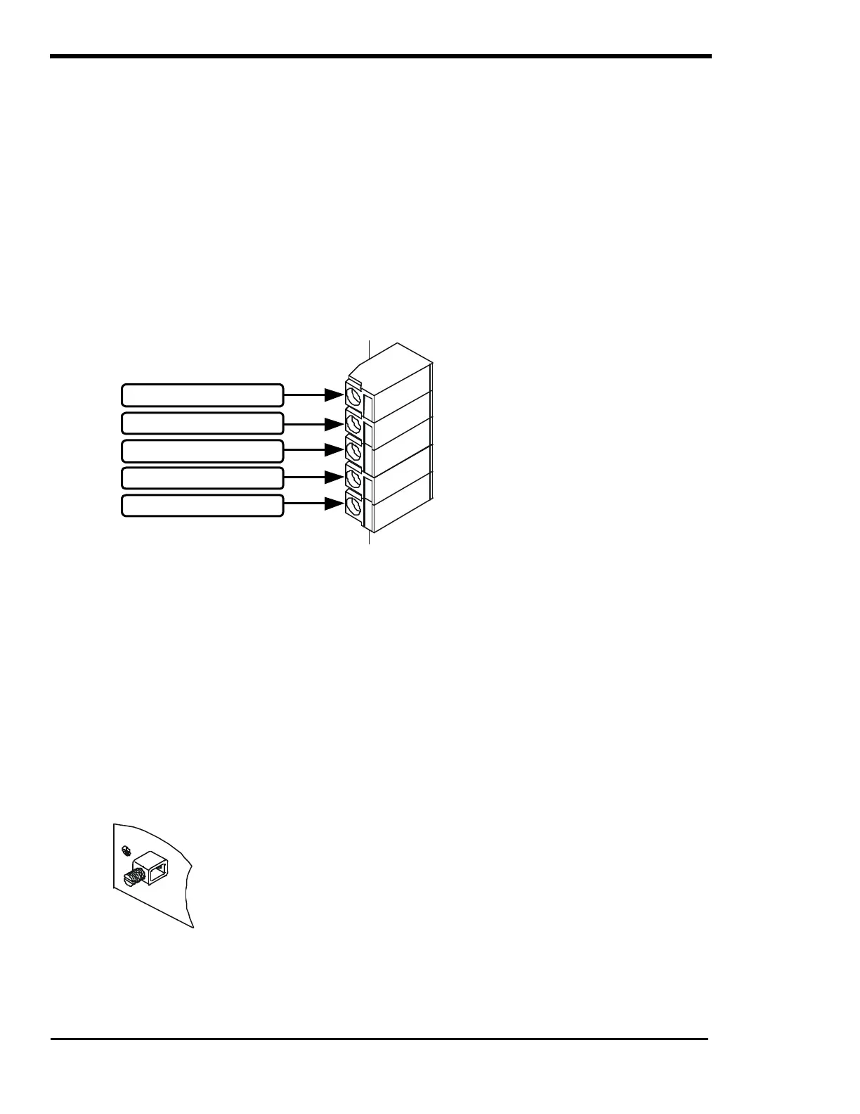
AC TERMINAL BLOCK
Figure 7, AC Terminal Block
A five pole terminal block is provided for hardwiring the inverter’s AC output the AC input connections. It
is located on the left-hand side of the inverter, enclosed under the access panel. The terminal block will
accept wire up to #6 AWG.
Depending on your unit’s configuration (See the UNIT IDENTIFICATION section on page 7 to determine
your unit’s particular configuration) the AC input and output neutrals are configured differently.
This manual is specific to models designed for use in Alternative Energy or Back-Up Power systems in
permanent structures, such as homes and commercial buildings. All of the PS Series units marked with the
Alternative Energy configuration are designed with the three NEUTRAL terminals being common to each
other and can be used in any combination or order. It is often simpler to only connect one AC neutral wire to
the inverter and make the other neutral connections at a central point such as at an AC load center, etc. The
additional AC NEUTRAL OUTPUT is provided for use when installing the optional Branch Breaker Kit.
AC GROUND TERMINAL
Figure 8, AC Ground Terminal
The AC Safety Ground Terminal - assessable through the AC access
cover - is used to connect the exposed chassis of the inverter to the
AC grounding system. This terminal accepts wires from #14 AWG to
#2 AWG.
AC HOT OUTPUT
AC NEUTRAL OUTPUT
AC NEUTRAL INPUT
AC HOT INPUT
AC NEUTRAL OUTPUT