TECHNICAL INFORMATION
Copyright Trace Engineering Company, Inc.
5916 - 195th Street N.E.
Arlington, WA 98223
Telephone: 360/435-8826
Fax: 360/435-2229
www.traceengineering.com
PS Series Inverter/Charger
Part No. 3597
Rev. D: November 23, 1999
Page
117
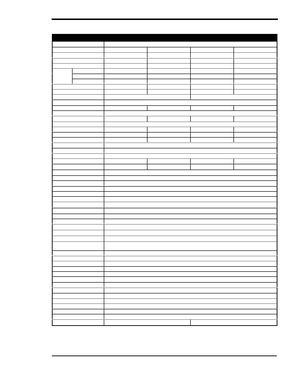
SPECIFICATIONS AND FEATURES
MODEL PS2512 PS2524 PS2212E PS2524E
General Specifications
Continuous Power @ 25°C
2500 VA 2500 VA 2200 VA 2500 VA
Continuous Output @ 25°C 21 amps AC 21 amps AC 9.5 amps AC 11 amps AC
Nominal DC Input Voltage 12 vdc 24 vdc 12 vdc 24 vdc
AC Output (RMS) 120 VAC / 60 Hz 120 VAC / 60 Hz 230 VAC / 50 Hz 230 VAC / 50 Hz
Light bulb (1) 4000 Watts 5000 Watts 3500 Watts 4500 Watts
1 mSec (2) 70 amps peak 90 amps peak 35 amps peak 45 amps peak
Surge
Capability
100 mSec (3) 40 amps RMS 50 amps RMS 20 amps RMS 25 amps RMS
Maximum Output (Peak) 45 amps AC 45 amps AC 45 amps AC 45 amps AC
Peak Efficiency 90% 92% 90% 92%
Max AC input / AC pass through 30 or 50 amps AC (via selector switch) 15 or 30 amps AC (via selector switch)
Battery Charger
Maximum Charging Rate 130 amps DC 65 amps DC 100 amps DC 65 amps DC
Charging Type 3 stage charger with temperature compensation (adjustable setpoints via SWRC or SWCA)
Charger Power Requirement
20 amps AC 20 amps AC 8 amps AC 10 amps AC
Charger Power Factor Power Factor Corrected / Low current distortion - 1.00 to 0.95 PF typical
Bulk Voltage (default) 14.4 VDC 28.8 VDC 14.4 VDC 28.8 VDC
Float Voltage (default) 13.4 VDC 26.8 VDC 13.4 VDC 26.8 VDC
Absorption Time (default) 2 hours 2 hours 2 hours 2 hours
DC Input Requirements
Search Mode Less than ½ watt
On Mode (no load - idle) 20 watts typical
At Full Rated Power 275 amps @ 12.6 VDC 140 amps @ 25.2 VDC 240 amps @ 12.6 VDC 140 amps @ 25.2 VDC
Input Voltage Range 11.8 to 16.5 VDC 22 to 33 VDC 11.8 to 16.5 VDC 22 to 33 VDC
AC Output Characteristics
AC Output Waveform Sinewave, 34 to 52 steps per cycle
Voltage Regulation ± 5%
Total Harmonic Distortion 3 to 5% (stand alone operation)
Power Factor Allowed -1 to +1
Frequency Regulation
± 0.04% (crystal regulated)
Load Sensing Range 16 watts default (adjustable from 16 to 240 watts – requires SWRC or SWCA)
Standard Features
Adjustable low battery protection
Battery Temperature Sensor
Variable brushless DC cooling fan
Grid interactive capable – requires SWRC or SWCA to enable the inverter to “sell” power
Options
SWRC
Full function remote control with LCD display for all PS Series inverters.
SWRC (25’ cable), SWRC/50FT (50’ cable)
SWCA Communications Adapter, allows PC or modem connection
RC8 On/Off remote control with status LED indicator (10, 25, 50 and 100 foot lengths available)
SWI (requires two inverters) Series stacking cable for dual PS series inverter systems for 120/240 VAC – 60 Hz output
SWI/PAR or SWI/PAR/E Paralleling kit for double power at 120 VAC / 60 Hz (SWI/PAR) or 230VAC / 50 Hz (SWI/PAR/E).
PSCB Conduit box for all PS Series inverters, fits on AC or DC end of inverter
Physical
Enclosure Type Indoor, ventilated, aluminum chassis with powdercoat finish and screened openings
Specified Temp Range 32°F to 104°F (0°C to 40°C) (output will meet specified tolerances)
Allowed Temperature Range -40°F to 140°F (-40°C to 60°C) (output may not meet specified tolerances)
Dimensions - Inverter Only (4) 15.25” (38.7 cm) high x 22.5” (57.1 cm) wide x 6.5” (16.5 cm) deep
Dimensions - Shipping 20” (52 cm) high x 26” (66 cm) wide x 12.75” (32.3 cm) deep
Weight - Inverter Only 80 lbs (42 kg )
Weight - Shipping 86 lbs (44 kg)
Approvals UL1741 / cUL to CSA 107.1 CE compliance
Notes:
(1) Surge "light bulb" - Maximum total nameplate light bulb wattage started from a cold start and powered for at least 1 minute
(2) Surge "1 mSec" - Maximum 1 ms peak output amps measured when starting AC loads
(3) Surge "100 mSec" - Maximum 100 ms peak output amps measured when starting AC loads
(4) Includes 2" (5 cm) H for mounting rails and 1.5" (3.8 cm) W for DC terminals