APPENDIX
Copyright Trace Engineering Company, Inc.
5916 - 195th Street N.E.
Arlington, WA 98223
Telephone: 360/435-8826
Fax: 360/435-2229
www.traceengineering.com
PS Series Inverter/Charger
Part No. 3597
Rev. D: November 23, 1999
Page
131
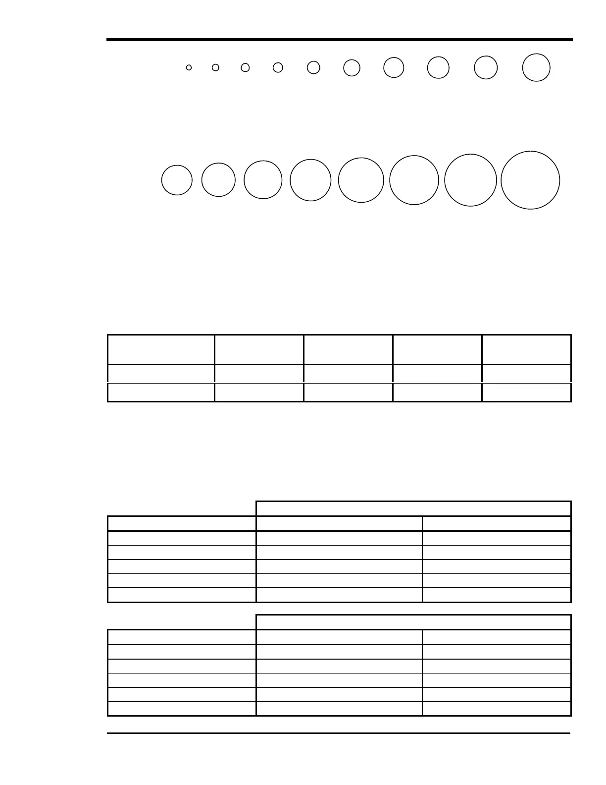
Note: Stranded wire sizes
Figure 41, AWG Wire Size
Table 13, Battery Cable to Maximum Breaker/Fuse Size
CABLE SIZE
REQUIRED
RATING IN
CONDUIT
MAXIMUM
BREAKER SIZE
RATING IN
“FREE AIR”
MAXIMUM
FUSE SIZE
00 AWG 175 amps 175 amps 265 amps 300 amps*
0000 AWG 250 amps 250 amps** 360 amps 400 amps*
* The NEC allows rounding up to the next standard fuse size from the cable rating, i.e. 150-amp
cable size rounds up to a standard 175-amp size. The term "free air" is defined by the NEC as
cabling that is not enclosed in conduit or a raceway. Cables enclosed in raceways or conduits have
substantially lower continuous current carrying ability due to heating factors.
** Nuisance tripping is possible if operated at 2.5 kVA continuously with a 250-amp breaker
Table 14, AC Input Default Settings
‘MAXIMUM AC AMPS IN’ SWITCH POSITION (120 VAC Models)
INPUT PROVISIONS AC1 AC2
Inverter Lower Limit (VAC) 108 108
Inverter Upper Limit (VAC) 132 132
AC Input Current (AC Amps) 50 30
Frequency (Hz) 53 – 67 (SELL mode = 59 – 61) 53 – 67
Delay Period (seconds) 20 (SELL mode = 90) 60
‘MAXIMUM AC AMPS IN’ SWITCH POSITION (230 VAC Models)
INPUT PROVISIONS AC1 AC2
Inverter Lower Limit (VAC) 206 206
Inverter Upper Limit (VAC) 254 254
AC Input Current (AC Amps) 25 15
Frequency (Hz) 43 – 57 (SELL mode = 49 – 51) 43 – 57
Delay Period (seconds) 20 (SELL mode = 90) 60
.475
.530
.580
.635
.690
.730
.820
.335
.380
.420
.072
.115
.146
.184
.235
.281
.295
.073
DIAMETER
DIAMETER