TECHNICAL INFORMATION
Page
120
Copyright Trace Engineering Company, Inc.
5916 - 195th Street N.E.
Arlington, WA 98223
Telephone: 360/435-8826
Fax: 360/435-2229
www.traceengineering.com
PS Series Inverter/Charger
Part No. 3597
Rev. D: November 23, 1999
INSTALLATION DIAGRAMS
The following diagrams and information is provided to assist you or your system installer with the design
and installation of the Trace PS Series Inverter/Charger. Due to the variety of applications, models
available, and differences in local and national electrical codes, these diagrams and information should
be used as general guidelines only. You must consider your application and local and national electrical
codes when designing and installing your system.
For more information, please contact your Trace dealer/distributor or contact Trace Engineering directly.
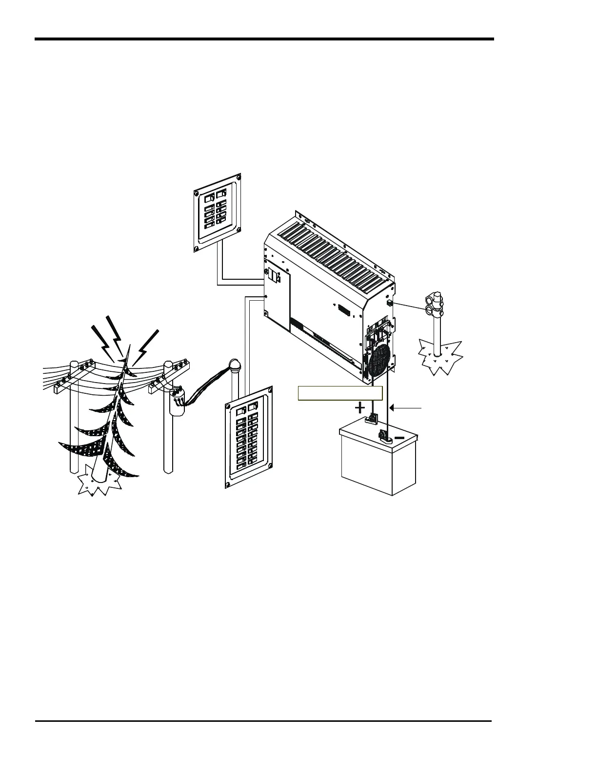
Figure 39, PS Series Installation Diagram – Stationary Backup System
loads connected to this
panel will be available
if utility power fails
PS Series Inverter
loads connected to this
panel will lose power if
utility power fails
See Table 3,
page 26 for
recommended
cable size in
conduit.