CONTROLS, INDICATORS AND COMPONENTS
Copyright Trace Engineering Company, Inc.
5916 - 195th Street N.E.
Arlington, WA 98223
Telephone: 360/435-8826
Fax: 360/435-2229
www.traceengineering.com
PS Series Inverter/Charger
Part No. 3597
Rev. D: November 23, 1999
Page
9
CONTROLS, INDICATORS AND COMPONENTS
Shown below are the controls and indicators on the PS Series Inverter/Charger. They enable you to
control and monitor the operating mode and system status of your inverter/charger. The controls on the
PS Series Inverter/Chargers are very straightforward. They feature a momentary On/Off Power switch, an
inverting/charger circuit breaker, four LED status indicators, a two-position switch for determining
maximum AC input current level and connecting ports for other optional accessories.
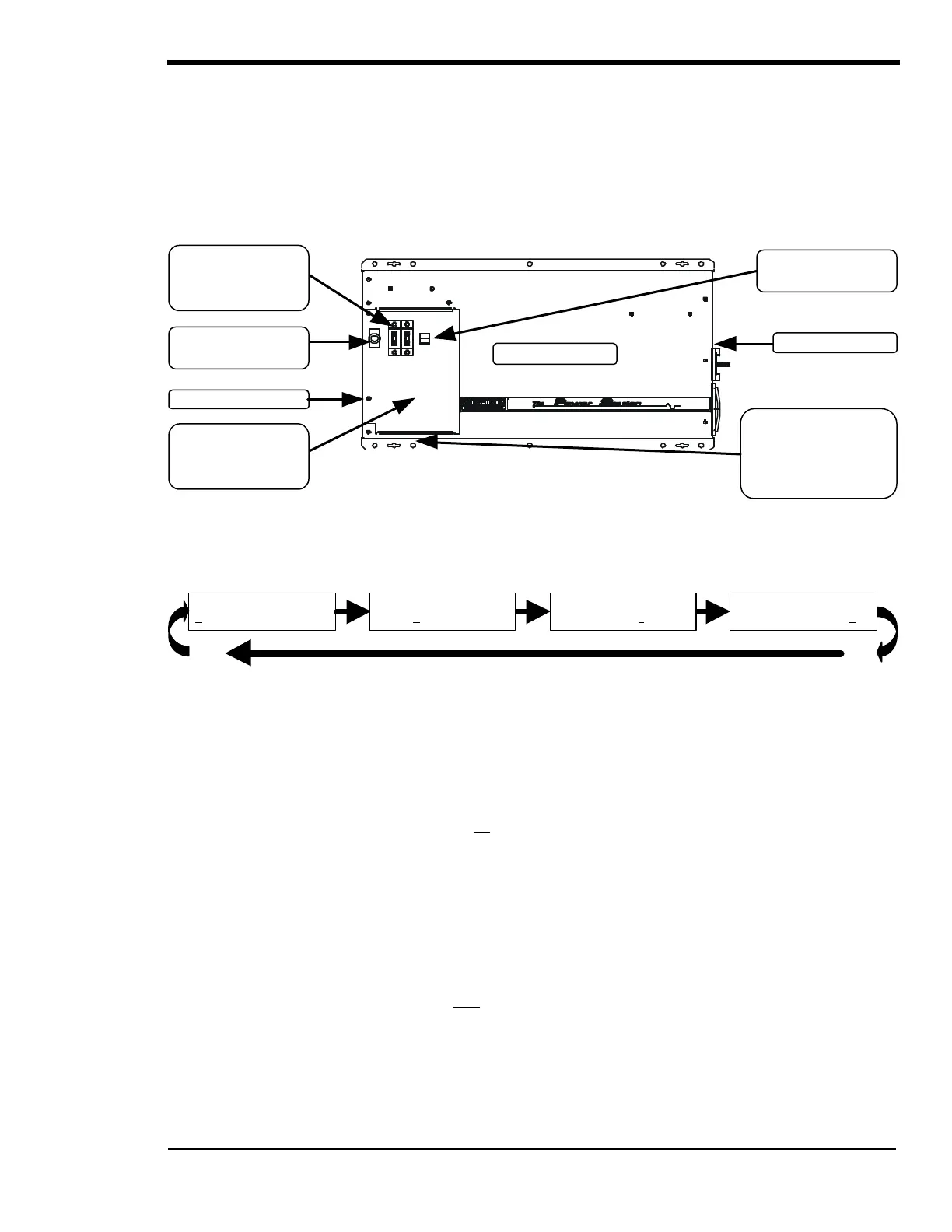
The figure below shows the location of the different controls and the Status Indicators.
Figure 3, Inverter Controls and Indicators
ON/OFF POWER SWITCH
This switch allows turning the inverter ON and OFF, enabling the SEARCH mode or selecting the charger
only mode CHG. The on/off button also resets the inverter in the event it shuts down completely due to a
fault condition. The inverter always starts in the OFF position when powered up. Each push changes the
mode you are in, continue pressing the ON/OFF power switch until you have your desired selection.
Monitor the INVERT (yellow) LED to determine what mode you have selected.
• OFF: Disables the inverter. This is the default position of the inverter upon power-up. When the
OFF position is selected, no power will be provided to the AC loads even if an AC source is
available. The red ERROR LED will be on, this indicates that there is no AC available on the output
and the INVERT (yellow) LED will be off.
• SRCH: Enables the automatic load search mode control system. This system will turn on the
inverter if a large enough load is connected. If not enough AC loads are detected, the INVERT
(yellow) LED will blink slowly (one blink/sec). No power will be provided to the AC loads, even if an
AC source is available. The sensitivity threshold is defaulted to 48 watts.
• ON: Allows the inverter to provide AC voltage to the output and energize the AC loads either from the
battery or from any “synchronized” AC source available on the input. The INVERT (yellow) LED will be on.
• CHG: Allows the inverter to operate only as a battery charger. AC power will be available to the AC
loads only if an AC source is available and “synchronized”. This mode is used to prevent discharge of
the batteries by the AC loads when a utility outage occurs. The INVERT (yellow) LED will double blink
each second (double blink/sec) to indicate that you are in CHG mode. This mode is only available
when the SET GRID USAGE menu item is in the FLT mode under the INVERTER SETUP (9) menu
heading. When a different mode is selected, this position will be locked out and it will be necessary to
use the SET POINTS buttons on the optional SWRC remote to move the cursor. Selecting the CHG
mode disables the Automatic Generator Start features.
SET INVERTER
OFF SRCH ON CHG
SET INVERTER
OFF SRCH ON CHG
SET INVERTER
OFF SRCH ON CHG
SET INVERTER
OFF SRCH ON CHG
Amps In’
Switch and LED
Status Indicators
Switch
Branch Circuit
Breakers
(Optional)
(Inside, under
Access Panel)
AC Circuit Breaker.