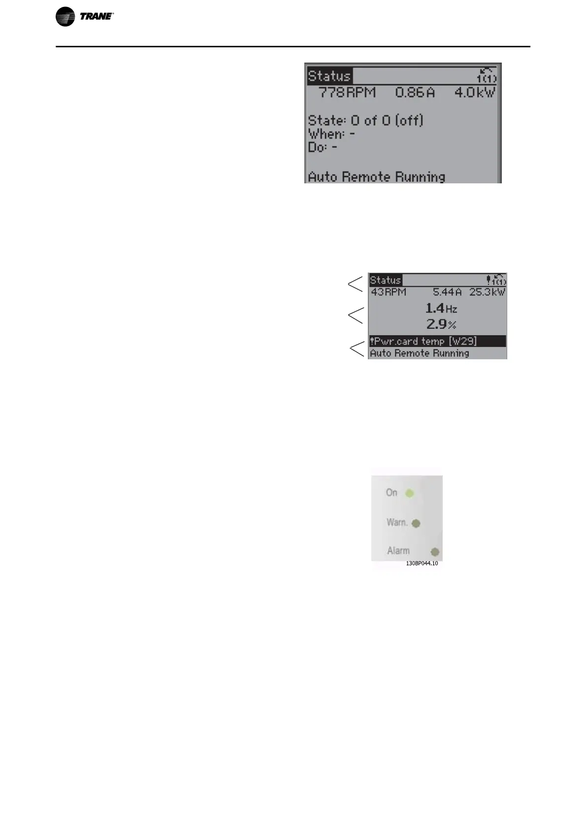
Status display III:
This state displays the event and action of the Smart
Logic Control. For further information, see section
Smart Logic Control
.
1
Display Contrast Adjustment
Press [status] and [
▲
] for darker display
Press [status] and [
▼
] for brighter display
130BP074.10
Top section
Middle section
Bottom section
Indicator lights (LEDs):
If certain threshold values are exceeded, the alarm and/or warning LED lights up. A status and alarm text appear
on the control panel.
The On LED is activated when the frequency converter receives power from mains voltage, a DC bus terminal,
or an external 24 V supply. At the same time, the back light is on.
• Green LED/On: Control section is working.
• Yellow LED/Warn.: Indicates a warning.
• Flashing Red LED/Alarm: Indicates an alarm.
How to Program
22 TR200 Programming Guide

 Loading...


