The display is divided into 3 sections:
Top section (a) shows the status when in status mode or up to 2 variables when not in status mode and in the
case of Alarm/Warning.
The number of the Active Set-up (selected as the Active Set-up in par.0-10
Active Set-up) is shown. When pro-
gramming in another Set-up than the Active Set-up, the number of the Set-up being programmed appears to
the right in brackets.
The Middle section (b) shows up to 5 variables with related unit, regardless of status. In case of alarm/warning,
the warning is shown instead of the variables.
The Bottom section (c) always shows the state of the frequency converter in Status mode.
It is possible to toggle between three status read-out displays by pressing the [Status] key.
Operating variables with different formatting are shown in each status screen - see below.
Several values or measurements can be linked to each of the displayed operating variables. The values / meas-
urements to be displayed can be defined via par.0-20
Display Line 1.1 Small, par.0-21 Display Line 1.2 Small,
par.0-22
Display Line 1.3 Small, par.0-23 Display Line 2 Large and par.0-24 Display Line 3 Large, which can be
accessed via [QUICK MENU], "Q3 Function Setups", "Q3-1 General Settings", "Q3-13 Display Settings".
Each value / measurement readout parameter selected in par.0-20
Display Line 1.1 Small to par.0-24 Display
Line 3 Large has its own scale and number of digits after a possible decimal point. Larger numeric values are
displayed with few digits after the decimal point.
Ex.: Current readout
5.25 A; 15.2 A 105 A.
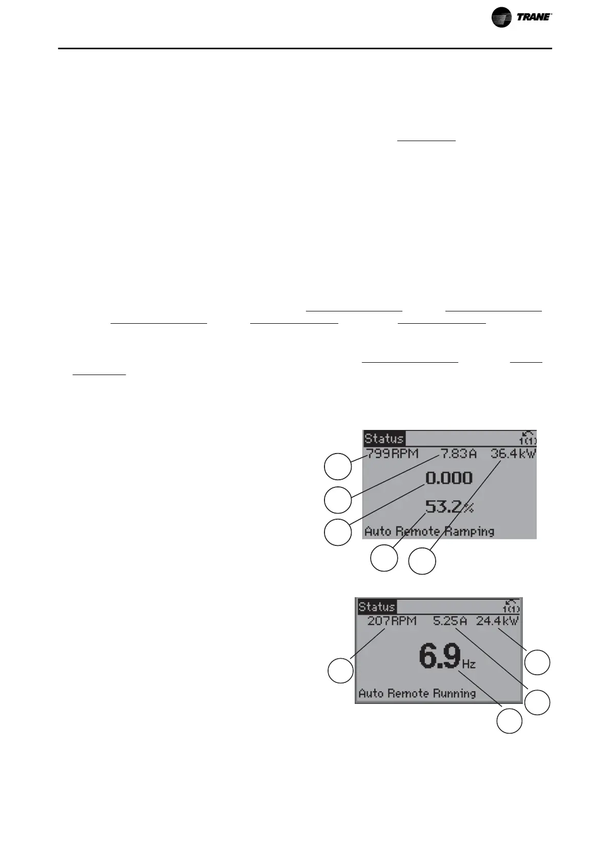
Status display I:
This read-out state is standard after start-up or initi-
alization.
Use [INFO] to obtain information about the value/
measurement linked to the displayed operating vari-
ables (1.1, 1.2, 1.3, 2, and 3).
See the operating variables shown in the display in
this illustration. 1.1, 1.2 and 1.3 are shown in small
size. 2 and 3 are shown in medium size.
130BP041.10
1.1
1.3
2
1.2
3
Status display II:
See the operating variables (1.1, 1.2, 1.3, and 2)
shown in the display in this illustration.
In the example, Speed, Motor current, Motor power
and Frequency are selected as variables in the first
and second lines.
1.1, 1.2 and 1.3 are shown in small size. 2 is shown in
large size.
130BP062.10
2
1.2
1.3
1.1
How to Program
TR200 Programming Guide 21

 Loading...


