4-5* Adj. Warnings
Define adjustable warning limits for current, speed, reference and feedback.
Note
Not visible in display, only in Trane Drive Utility.
Warnings are shown on display, programmed output or serial bus.
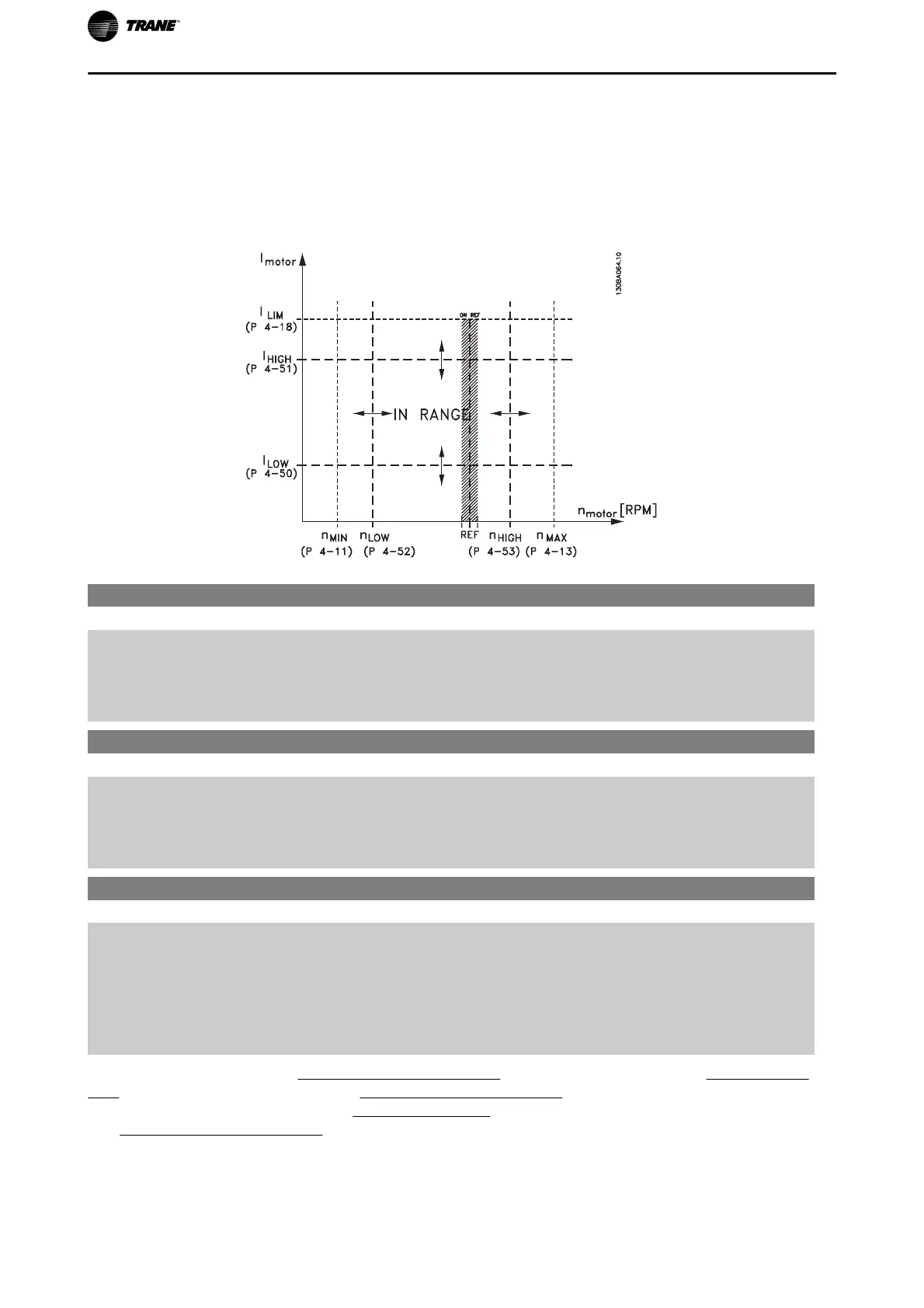
4-50 Warning Current Low
Range: Function:
0.00 A* [0.00 - par. 4-51 A] Enter the I
LOW
value. When the motor current falls below this limit
(I
LOW
), the display reads CURRENT LOW. The signal outputs can be
programmed to produce a status signal on terminal 27 or 29 and on relay
output 01 or 02. Refer to the drawing in this section.
4-51 Warning Current High
Range: Function:
par.
16-37 A*
[par. 4-50 - par. 16-37 A] Enter the I
HIGH
value. When the motor current exceeds this limit
(I
HIGH
), the display reads CURRENT HIGH. The signal outputs can be
programmed to produce a status signal on terminal 27 or 29 and on relay
output 01 or 02. Refer to the drawing in this section.
4-53 Warning Speed High
Range: Function:
par. 4-13
RPM*
[par. 4-52 - par. 4-13 RPM] Enter the n
HIGH
value. When the motor speed exceeds this limit
(n
HIGH
), the display reads SPEED HIGH. The signal outputs can be pro-
grammed to produce a status signal on terminal 27 or 29 and on relay
output 01 or 02. Programme the upper signal limit of the motor speed,
n
HIGH
, within the normal working range of the frequency converter. Re-
fer to the drawing in this section.
NOTE: Any changes in par.4-13
Motor Speed High Limit [RPM] will reset the value in par.4-53 Warning Speed
High to the same value as set in par.4-13 Motor Speed High Limit [RPM].
If a different value is needed in par.4-53
Warning Speed High, it must be set after programming of par.
4-13
Motor Speed High Limit [RPM]!
Parameter Description
84 TR200 Programming Guide

 Loading...


