Enkapsis & EnerSure Platform Installation Guide Rev07.2
Figure 34: CT Connected to Circuit
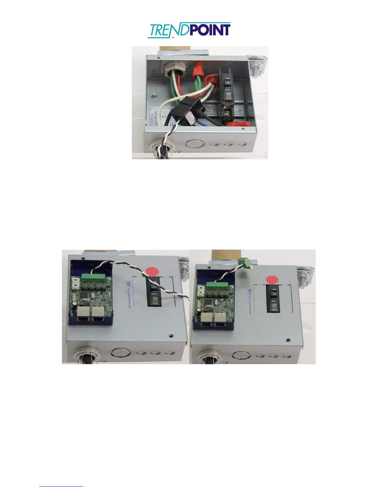
3.) Feed the CT wires through the Bus Tap Card feed-though (Figure 35) and
connect to the 8-pin connector on the Bus2.0 Card. The CT wires may be cut
to length. (See CT Wiring for CT and connector order.)
Note: Connectors may be used to allow the Bus2.0 Case to be completely
removed without unsnapping the CT’s.
Figure 35: CT wires fed through the Bus2.0 Card, cut to length and connected
to CT connector
4.) When all CT connections have been made, the Bus2.0 Card address must be
set. To set the card, use the 10 position selector switches (Figure 36) to set
the applicable address.
NOTE: The card should be set to an address between 1 and 48. Page 57 of this
installation guide contains a matrix to indicate the address selection and the relation
to the circuit numbers.