Enkapsis & EnerSure Platform Installation Guide Rev07.2
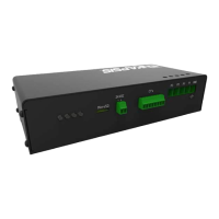
Figure 36: Bus2.0 Card showing address switches
5.) Close the cover on the Bus2.0 Card by securing the thumb screw.
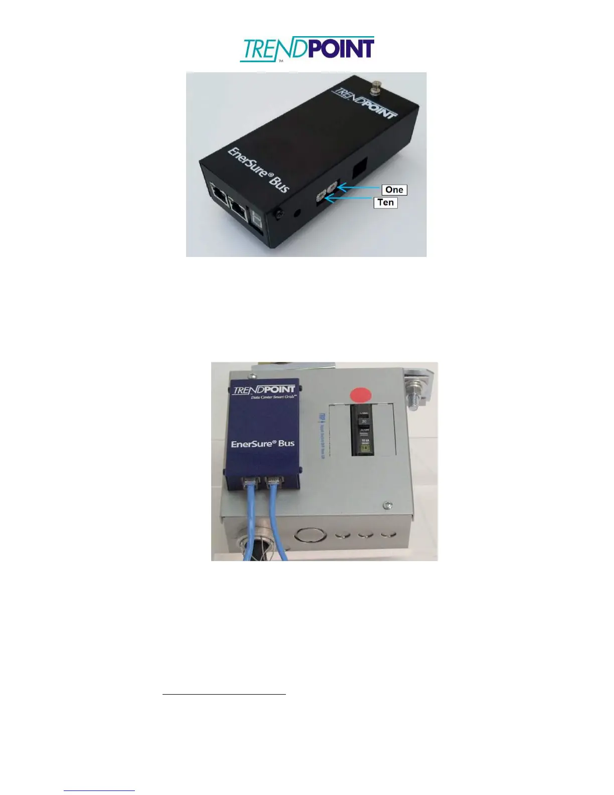
6.) The Bus2.0 Cards are connected via a straight-though Ethernet cable as
shown in Figure 37. The system uses all 8 wires on the Ethernet cable.
Figure 37: Ethernet Cables Connected
7.) Connect the Bus2.0 Cards in a “daisy chain” format and link back to the Enkapsis
Bus port.
8.) Switch the input breaker to the “ON” position. The Bus2.0 system can be configured
via the Enkapsis Ethernet ports (Eth0 or Eth1) using the web interface. The data
from the Bus2.0 is available via Modbus TCP/IP, SNMP, and BACnet.
Default TCP/IP Settings:
IP: 10.10.10.4
Subnet: 255.0.0.0
Gateway: 10.10.10.1