13 Setting up the Receiver
128 5700/5800 GPS Receiver User Guide
5800 Operation
Each port or connector on the 5800 receiver is marked with an icon to
indicate its main function, as shown in Table 13.1.
Port 1 is a 7-pin 0-shell LEMO connector that supports RS-232
comms and external power input. Port 1 has no power outputs.
Port 2 is a DB-9 male connector that allows for full 9-pin RS-232
comms. Port 2 does not support power in or out. For more information
on default port settings, see Default Settings, page 167. For more
information on connector pinouts, see Cables and Connectors,
page 169.
The TNC port connector is for connecting a radio antenna to the 5800
internal radio. A whip “rubber duck” antenna is supplied with the
system for units with internal UHF or 900 MHz radios. This connector
is not used if you are using an external radio receiver. For more
information on connecting the 5800 receiver, see the following
sections in this chapter.
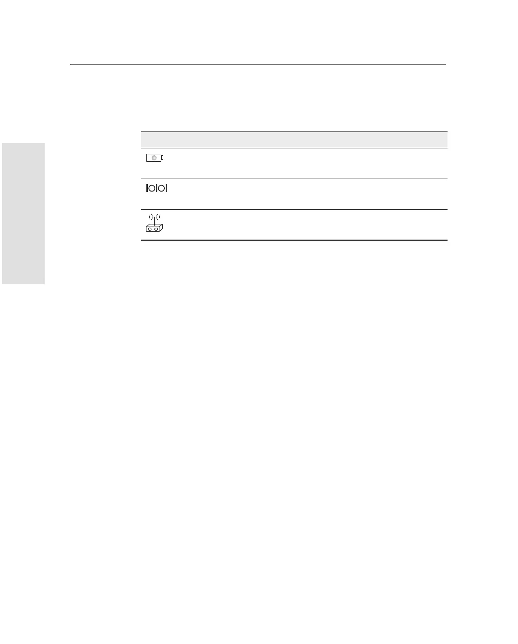
Table 13.1 5800 receiver ports
Icon Name Connections
Port 1 Device, computer, external radio, power in
Port 2 Device, computer, external radio
RADIO Radio communications antenna