4-12
4.12 COMFORT CONTROL CENTER
A comfort control center is located in the motorhome (living area
or bedroom) to control the heating and cooling systems in the
vehicle. The control center is customized to the specications of
your vehicle and will control one or more furnaces and air condi-
tioners.
Review the operator's manual in the information package for
detailed operating instructions. The control functions include:
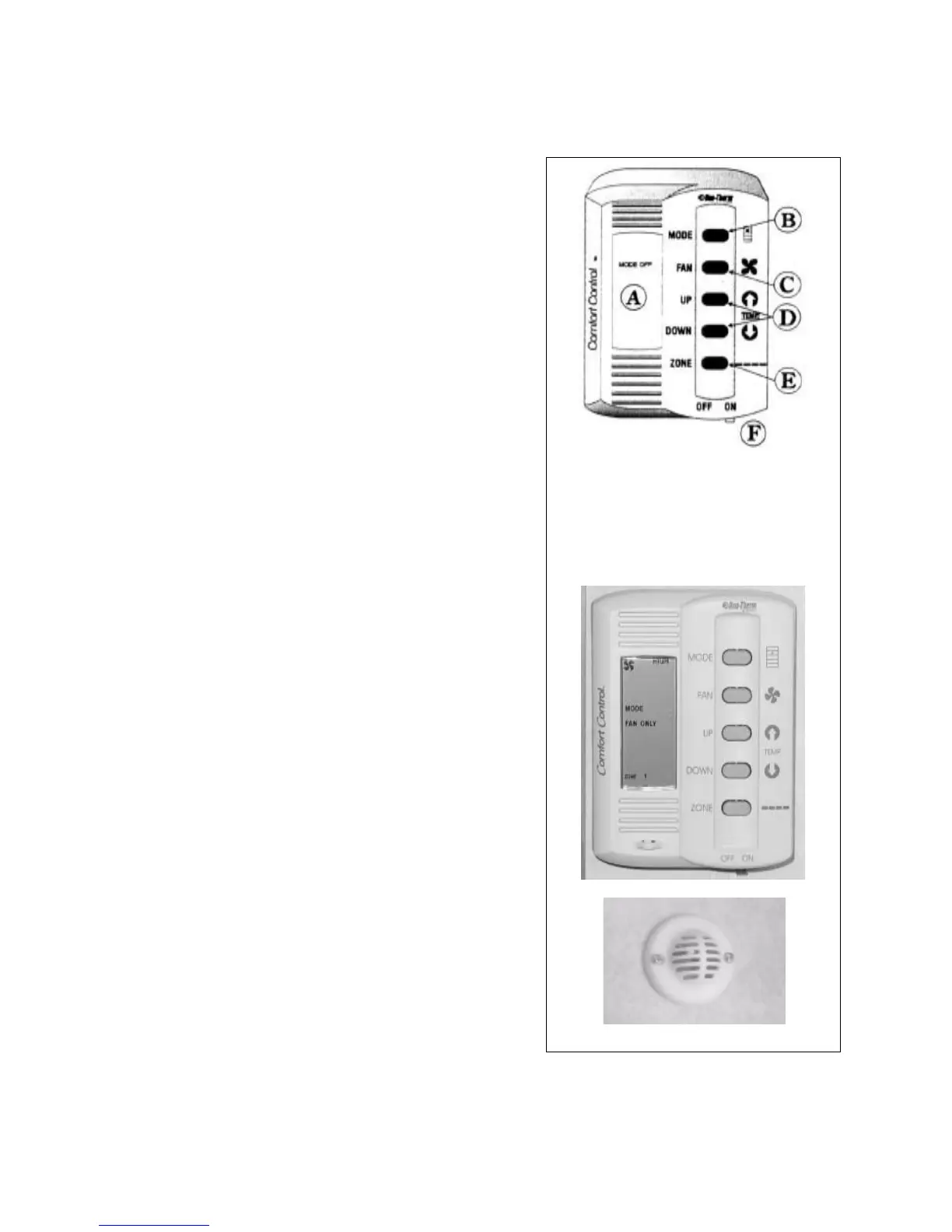
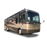
1. Liquid Crystal Display (A):
This liquid crystal display shows the operator the specic
operating parameters of the comfort appliances. The display
will change to reect the varying operating selections by the
user.
2. Mode Selector Button (B):
This push button switch controls the selection of the system
operating mode. Depress the switch momentarily to step
the fan, cool, furnace and heat strip. Depress the switch
again momentarily to move to the next selection. The mode
selected will show in the Liquid Crystal Display.
3. Fan Speeds (C):
This push button switch controls the settings for fan speed
and mode. Depress the switch momentarily to step the fan
through each setting from low, medium, high and auto.
Depress the switch again momentarily to move to the next
setting. The speed selection will show in the Liquid Crystal
Display.
4. Temperature Selector Buttons (Up and Down) (D):
These push buttons raise or lower the selected system
temperature. Depress the switch momentarily to change the
temperature. Continue to momentarily depress the switch to
change the desired temperate. The selected temperature will
show in the Liquid Crystal Display.
5. Zone and Stage Selector Buttons (E) Commander Only:
These push buttons select the individual zones and stages
for the system. Depress both buttons simultaneously in a
momentary manner to step the control system through its
choice of zones and stages. Zones refer to air conditioner
cooling areas and stages refer to heating areas. The selected
zones and stages will show in the Liquid Crystal Display.
6. On/O Switch (F):
This sliding lever switch is the master ON/OFF switch for the
comfort system. Move the lever to the left to turn o and to
the right for on.
A. Liquid Crystal Display
B. Mode Selector Button
C. Fan Speed Selector Button
D. Temperature Selector Buttons
E. Zone and Stage Selector
F. On/O Switch
Schematic
Control
Fig. 4-17 COMFORT CONTROL CENTER
COMMANDER / EMBASSY
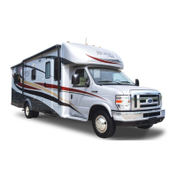
Zone Temperature Sensor
4-12
4.12 COMFORT CONTROL CENTER
A comfort control center is located in the motorhome (living area
or bedroom) to control the heating and cooling systems in the
vehicle. The control center is customized to the specications of
your vehicle and will control one or more furnaces and air condi-
tioners.
Review the operator's manual in the information package for
detailed operating instructions. The control functions include:
1. Liquid Crystal Display (A):
This liquid crystal display shows the operator the specic
operating parameters of the comfort appliances. The display
will change to reect the varying operating selections by the
user.
2. Mode Selector Button (B):
This push button switch controls the selection of the system
operating mode. Depress the switch momentarily to step
the fan, cool, furnace and heat strip. Depress the switch
again momentarily to move to the next selection. The mode
selected will show in the Liquid Crystal Display.
3. Fan Speeds (C):
This push button switch controls the settings for fan speed
and mode. Depress the switch momentarily to step the fan
through each setting from low, medium, high and auto.
Depress the switch again momentarily to move to the next
setting. The speed selection will show in the Liquid Crystal
Display.
4. Temperature Selector Buttons (Up and Down) (D):
These push buttons raise or lower the selected system
temperature. Depress the switch momentarily to change the
temperature. Continue to momentarily depress the switch to
change the desired temperate. The selected temperature will
show in the Liquid Crystal Display.
5. Zone and Stage Selector Buttons (E) Commander Only:
These push buttons select the individual zones and stages
for the system. Depress both buttons simultaneously in a
momentary manner to step the control system through its
choice of zones and stages. Zones refer to air conditioner
cooling areas and stages refer to heating areas. The selected
zones and stages will show in the Liquid Crystal Display.
6. On/O Switch (F):
This sliding lever switch is the master ON/OFF switch for the
comfort system. Move the lever to the left to turn o and to
the right for on.
A. Liquid Crystal Display
B. Mode Selector Button
C. Fan Speed Selector Button
D. Temperature Selector Buttons
E. Zone and Stage Selector
F. On/O Switch
Schematic
Control
Fig. 4-17 COMFORT CONTROL CENTER
COMMANDER / EMBASSY
Zone Temperature Sensor