6-7
6.4 REAR VIEW CAMERA/MONITOR
SYSTEM
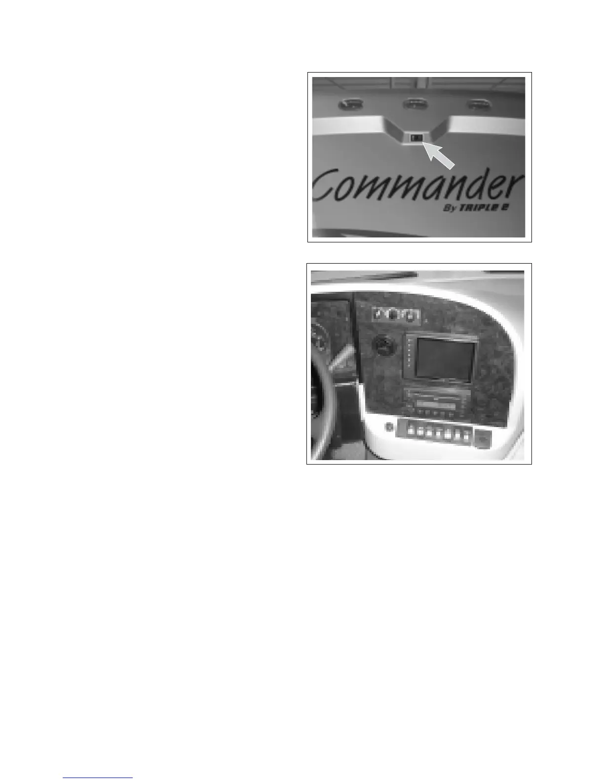
A rear view monitor camera is mounted on the back of
the unit to provide a view behind the unit.
1. Camera:
The camera is mounted to pick-up a view of the
area behind the unit for backing up or a trailer
that is being towed.
2. Monitor:
The monitor is mounted so it is visible to the
driver to assist in backing up or driving.
3. Operating Modes:
a. On/O:
In this mode, the system operates only when
the system is turned on. It is not recommend-
ed that it be operated on a full time basis
when driving as it can be very distracting.
b. Standby:
In this mode, the system automatically comes
on when the transmission is shifted into re-
verse to assist in backing up. It goes o when
the transmission is shifted back into drive.
4. Refer to the camera/monitor system manual for
more detailed operating and system instructions.
COMMANDER / EMBASSY
Fig. 6-8 MONITOR (TYPICAL)
Fig. 6-7 CAMERA LOCATION
6-7
6.4 REAR VIEW CAMERA/MONITOR
SYSTEM
A rear view monitor camera is mounted on the back of
the unit to provide a view behind the unit.
1. Camera:
The camera is mounted to pick-up a view of the
area behind the unit for backing up or a trailer
that is being towed.
2. Monitor:
The monitor is mounted so it is visible to the
driver to assist in backing up or driving.
3. Operating Modes:
a. On/O:
In this mode, the system operates only when
the system is turned on. It is not recommend-
ed that it be operated on a full time basis
when driving as it can be very distracting.
b. Standby:
In this mode, the system automatically comes
on when the transmission is shifted into re-
verse to assist in backing up. It goes o when
the transmission is shifted back into drive.
4. Refer to the camera/monitor system manual for
more detailed operating and system instructions.
COMMANDER / EMBASSY
Fig. 6-8 MONITOR (TYPICAL)
Fig. 6-7 CAMERA LOCATION