4-26
COMMANDER / EMBASSY
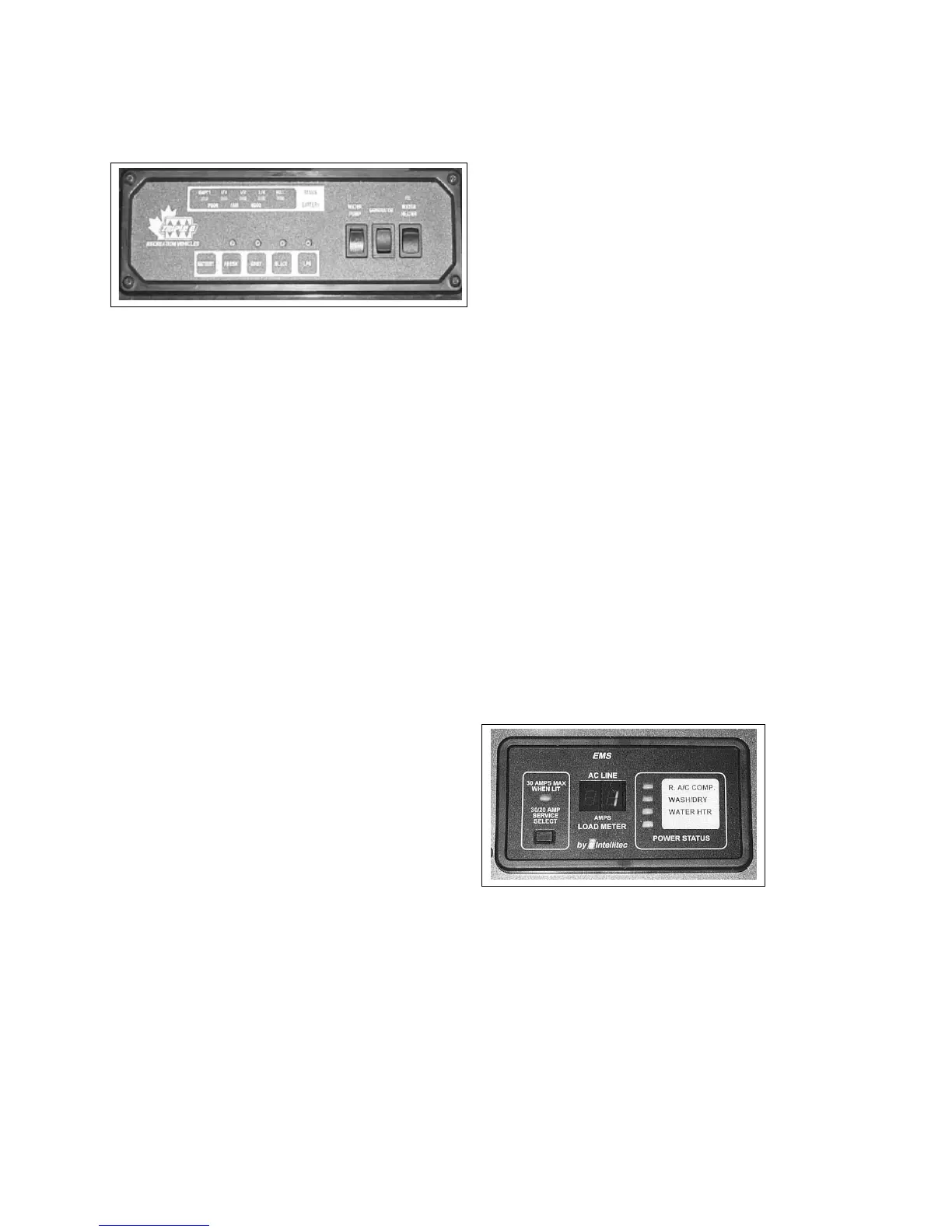
4.21 ENERGY MANAGEMENT SYSTEM
(EMS) OPTIONAL
This system prioritizes and distributes the power from
the shoreline or generator to the appliances or other
120 V users. This system disconnects selected “post-
pone-able” power draws to eliminate or minimize the
tripping of circuit breakers. The selected power draws
are automatically turned back on when the higher
priority power requirement is over.
The control panel is located above the coach en-
try doorway and the monitoring microprocessor is
mounted in the electrical AC breaker box. No setting
or adjusting by operator is required.
Normally the postpone-able power draws are the air
conditioner, washer/dryer and electric water heater.
Each will be shut down as other demands increase.
Refer to the booklet in the information package for
more details.
Fig. 4-38 EMS Control Panel
4.20 SYSTEM MONITOR
A system monitor is located aboce the entrace door-
way.
1. Status LED's:
Five LED's are used to indicate the status of the
tanks and battery. The tank scale registers EMPTY,
1/4, 1/2, 3/4 or FULL. The battery charge condition
registers POOR, FAIR and GOOD. Read the appro-
priate scale when the battery or tank switches are
depressed.
2. System Switches:
Each system is equipped with a switch to activate
its own monitoring system. Depress and hold the
switch. The system condition will be shown by the
LEDs above.
a. Coach Battery
b. Fresh Water Tank
c. Grey Water Tank
d. Black Water Tank
e. LP Gas Tank
3. Water Pump Master:
This rocker switch controls the power to the water
pump. Depress the top of the switch to turn the
power to the pump on. A red light in the switch
will come on when the power is on. Depress the
bottom of the switch to turn o and the light will
go o. When the power is on, the auxiliary water
pump switches can be used to turn the pump on
and o (Commander only). See 4.15.3 for more
information.
4. Generator:
This 3 position rocker switch controls the power to
the auxiliary generator.
a. Starting:
Depress the top portion of the switch against
the spring load to engage the starter and
start the engine. Release the switch when the
engine starts and it will return to the run posi-
tion.
b. Stopping:
Depress the bottom portion of the switch and
hold until the generator stops. Release the
switch.
Fig. 4-37 SYSTEM MONITOR
1
2
3
4
5
5. Water Heater:
This rocker switch controls the electrical power to
the water heater igniter. Depress the top part of
the switch and the water heater will ignite. The
red light in the switch will go o when the burner
ignites.
The red light will remain on if the burner fails to
ignite.
4-26
COMMANDER / EMBASSY
4.21 ENERGY MANAGEMENT SYSTEM
(EMS) OPTIONAL
This system prioritizes and distributes the power from
the shoreline or generator to the appliances or other
120 V users. This system disconnects selected “post-
pone-able” power draws to eliminate or minimize the
tripping of circuit breakers. The selected power draws
are automatically turned back on when the higher
priority power requirement is over.
The control panel is located above the coach en-
try doorway and the monitoring microprocessor is
mounted in the electrical AC breaker box. No setting
or adjusting by operator is required.
Normally the postpone-able power draws are the air
conditioner, washer/dryer and electric water heater.
Each will be shut down as other demands increase.
Refer to the booklet in the information package for
more details.
Fig. 4-38 EMS Control Panel
4.20 SYSTEM MONITOR
A system monitor is located aboce the entrace door-
way.
1. Status LED's:
Five LED's are used to indicate the status of the
tanks and battery. The tank scale registers EMPTY,
1/4, 1/2, 3/4 or FULL. The battery charge condition
registers POOR, FAIR and GOOD. Read the appro-
priate scale when the battery or tank switches are
depressed.
2. System Switches:
Each system is equipped with a switch to activate
its own monitoring system. Depress and hold the
switch. The system condition will be shown by the
LEDs above.
a. Coach Battery
b. Fresh Water Tank
c. Grey Water Tank
d. Black Water Tank
e. LP Gas Tank
3. Water Pump Master:
This rocker switch controls the power to the water
pump. Depress the top of the switch to turn the
power to the pump on. A red light in the switch
will come on when the power is on. Depress the
bottom of the switch to turn o and the light will
go o. When the power is on, the auxiliary water
pump switches can be used to turn the pump on
and o (Commander only). See 4.15.3 for more
information.
4. Generator:
This 3 position rocker switch controls the power to
the auxiliary generator.
a. Starting:
Depress the top portion of the switch against
the spring load to engage the starter and
start the engine. Release the switch when the
engine starts and it will return to the run posi-
tion.
b. Stopping:
Depress the bottom portion of the switch and
hold until the generator stops. Release the
switch.
Fig. 4-37 SYSTEM MONITOR
1
2
3
4
5
5. Water Heater:
This rocker switch controls the electrical power to
the water heater igniter. Depress the top part of
the switch and the water heater will ignite. The
red light in the switch will go o when the burner
ignites.
The red light will remain on if the burner fails to
ignite.