19
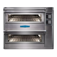
TEST MODE
Test Mode
To access the Test Mode:
1. While the oven is off or cooling, press the “i” key.
2. Press the Down arrow key to view the Info 2
screen (Figure 6, page 13).
3. Select “Test Mode.”
4. When prompted, enter the password 9 4 2 8 and
press the Enter key.
Test Mode is helpful for testing the oven circuits. By
default, idle airflow is set to 40%.
Status Indicators
The status indicators are located at the bottom of
the Test Mode screen:
- P = Primary switch (backlit = open)
- S = Secondary switch (backlit = open)
- M = Monitor switch (backlit = open)
- t = Magnetron thermostat (backlit = open)
- H1 = Top heater (backlit = off)
- H2 = Bottom heater (backlit = off)
- A = Air (blower motor) (backlit = off)
- W = Microwave (backlit = off)
In the Test Mode screen shown above:
- All three door switches (P, S, M) are closed.
- The top heater (H1) is off.
- The bottom heater (H2) is off.
- The blower motor (A) is on.
- The microwave circuit (W) is off.
Magnetron Test
To turn on the magnetrons, press and hold the key
adjacent to “Mag” (Figure 17). To turn them off,
release the key.
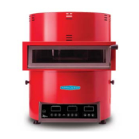
While holding the “Mag” key, measure the current
transformer wire on the control board (Figure 18)
for 13-15A (240 V) or 15-17A (208 V).
For more information on magnetron-related issues:
- See page 30 for additional testing options.
- See page 39 for F3 troubleshooting.
- See page 40 for F5 troubleshooting.
Blower Motor Test
Press the key adjacent to “Blower” (Figure 19) to
increase the blower motor speed in 10% increments.
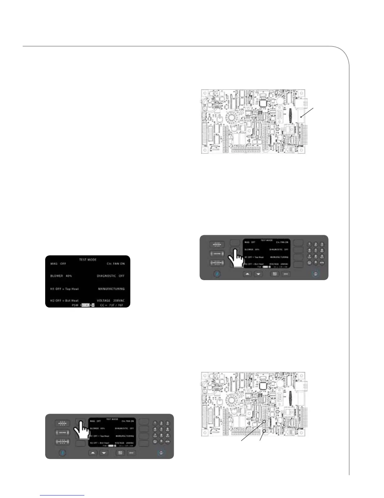
Test for voltage on the J1 and J2 connector:
1. Ground pin 5 of the J1 connector.
2. While pin 5 is grounded, check the terminals
on the control wiring plug for 0-10 VDC across
pins 1 and 2 of the J1 connector (Figure 20)
while increasing the blower speed. The
measurement should increase appx. 1 VDC for
each 10% increase in blower speed, up to 100%
(10 VDC), which is approximately 7,000 RPM.
For troubleshooting an F1 fault, see page 37.
Current
Transformer
Pin 1: Measure
for 0-10 VDC
Pin 5: Ground
Figure 16: Test Mode Screen
Figure 17: Test Mode: Magnetron Test
Figure 18: CT Location on Control Board
Figure 19: Test Mode: Blower Test
Figure 20: Blower Test Points on Control Board