ZED-F9P-Integration Manual
UBX-18010802 - R02
8 Design Page 92 of 114
Advance Information
The UART1 interface that is connected to the Host will usually also have the RTCM messages
required for RTK operation transferred on it. The optional UART2 interface can only be used for
RTCM/NMEA messages and has no Host interface capabilities.
It is important to connect V_USB to ground if USB is not used.
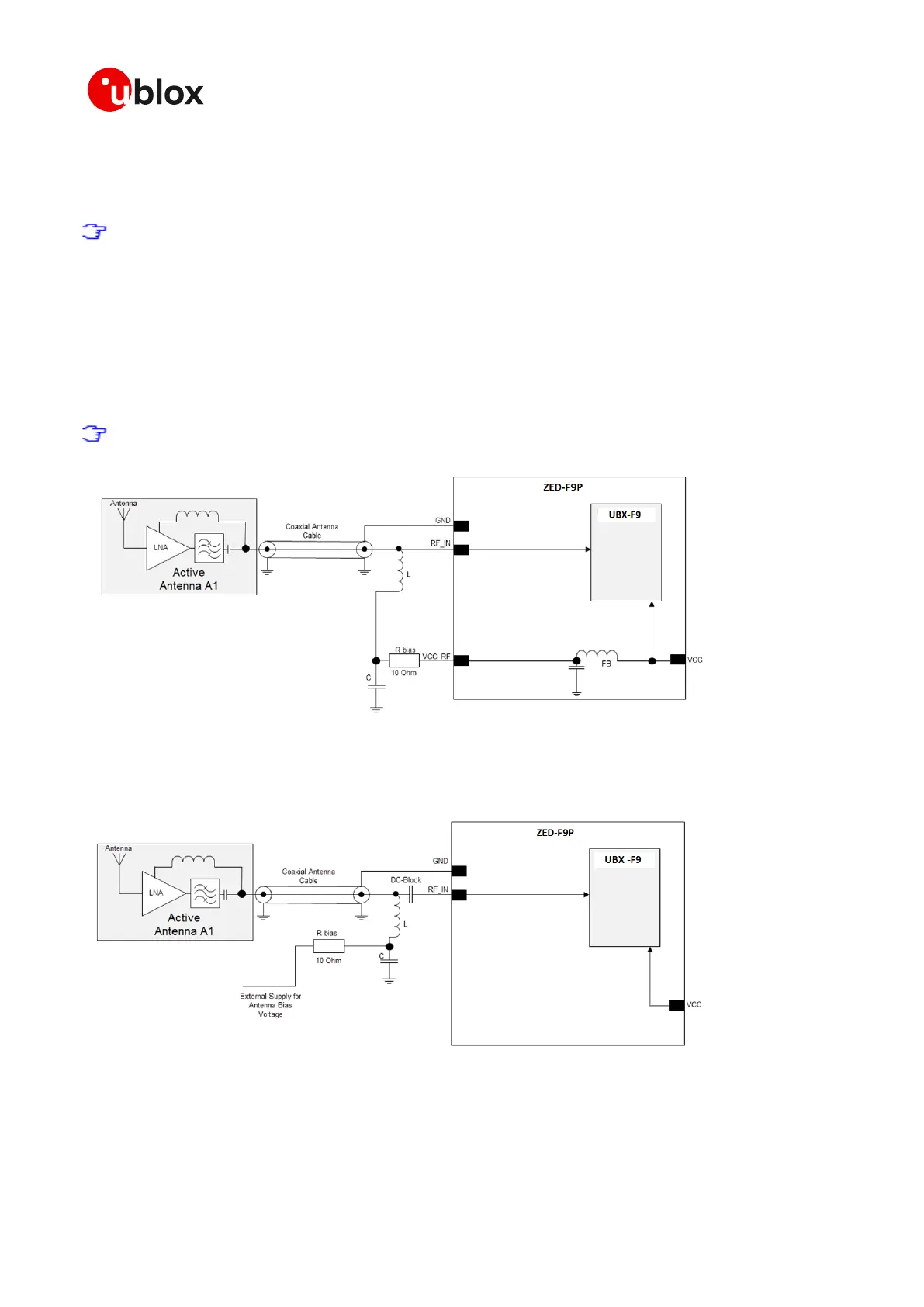
8.6 ZED-F9P antenna bias
Active antennas have an integrated low-noise amplifier. Active antennas require a power supply
that will contribute to the total GNSS system power consumption budget with additional 5 to 20
mA typically. If the customers do not want to make use of the Antenna Supervisor function and the
supply voltage of the ZED-F9P module matches the supply voltage of the antenna (e.g. 3.0 V), they
can use the filtered supply voltage VCC_RF output to supply the antenna. However a 10 Ω current
limiting resistor is required to prevent against short circuits destroying the BIAS-T inductor.
The bias-t inductor must be chosen for multi-band operation a value of 120 nH 5% is
recommended.
Figure 66: ZED-F9P VCC_RF antenna bias
If the VCC_RF voltage does not match with the supply voltage of the active antenna, use a filtered
external supply.
Figure 67: ZED-F9P external voltage antenna bias
The recommended circuit design for the active antenna bias using an external voltage and current
limiting circuit is shown below. This also includes ESD protection that must be implemented.
 Loading...


