ZED-F9P-Integration Manual
UBX-18010802 - R02
8 Design Page 87 of 114
Advance Information
The antenna system should include filtering to ensure adequate protection from nearby
transmitters. Care should be taken in the selection of antennas placed close to cellular or WiFi
transmitting antennas.
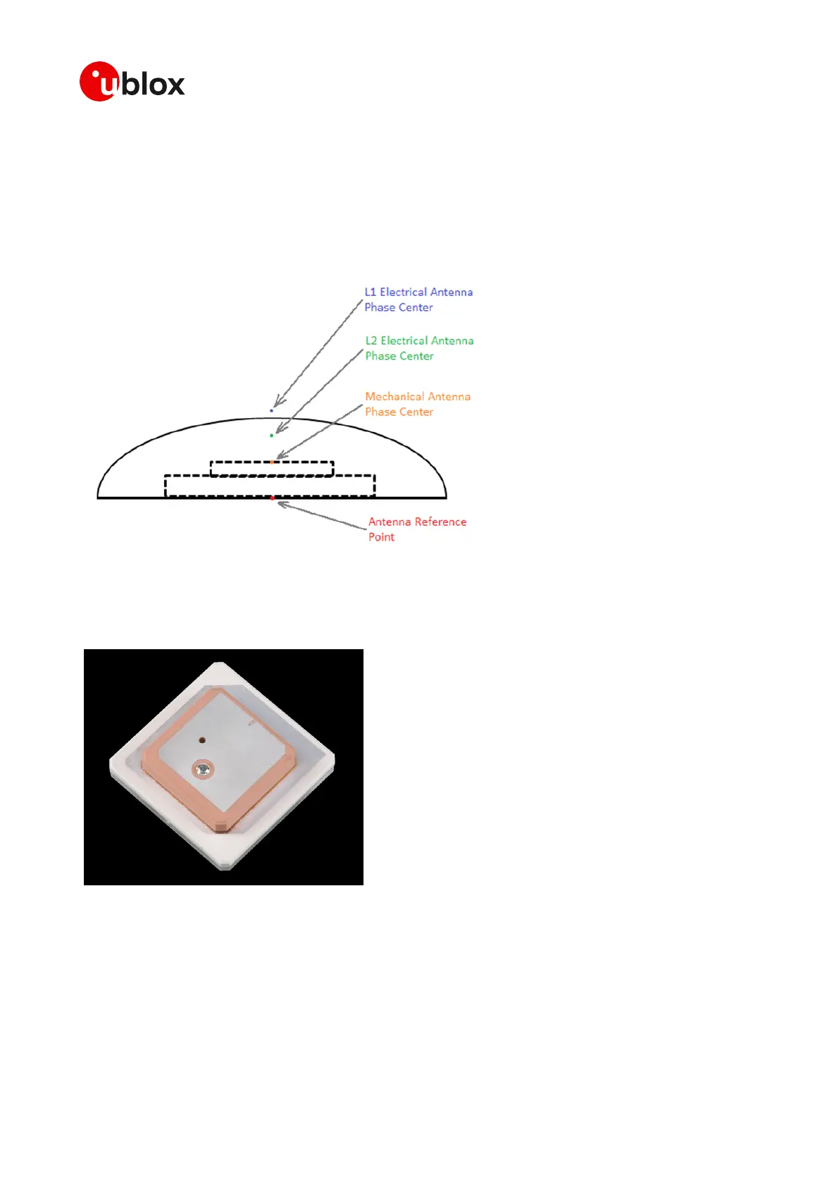
8.4 Stacked patch antenna
The typical L1 + L2 antenna will be a stacked patch antenna design. There will be a discrete L1 patch
on top of a L2 patch.
Figure 56: Stacked patch antenna
It is important to note that the absolute position of the antenna placement needs to be calculated
from the L1/L2 phase-variation. The L1 and L2 patch phase centers must vary to a minimum. The
final Antenna Reference point or ARP is then used to calculate the actual precise antenna position.
Figure 57: Ceramic Stack
If the antenna is to be used in an automotive application in mass production. The final placement of
the antenna will affect the Phase center variation, the antenna ground plane size and shape and the
antenna location to other bodies or structures will cause offsets. The final Phase center variation
calibration will need to be done on the final vehicle with the antenna in its final location. If the phase
variation of a specific antenna is repeatable between samples, the Phase center variation can be
calibrated successfully.
 Loading...


