Version 1
20
Note: If a storage location has been used during a test run, it will be highlighted in black with white let-
ters as shown:
On the bottom line of the Display Panel, you will find the Function Select Indicator: “Press Enter for:”
(you can use this to enter any of the following function fields) The default function fields are:
a. Exit main: Exits to main display.
b. Edit text: When on text notations can be set using up to 16 alphanumeric characters.
c. More: View additional test information including Date, Time and Module used.
d. Param info: View or change inspection details. It can also be set in the Applications Select menu
for specific application information such as Leak Info, Bearing Info, Steam Info, Electric Info, Valve
Info)
e. Record wav: The Ultraprobe 10000 is configured to record heterodyned ultrasounds with this
function setting.
f. CF info (compact flash): Information of stored recorded WAV files and record time can be viewed
here.
g. Store rec: Use this function to store inspection data. This is a quick way to data log if inspection
data is to be saved without viewing previously stored data (as in Storage Display).
Storage Display Information
When in the Storage Display mode, the basic inspection parameter information can be viewed and
stored if desired. To view Parameter Information when in the Storage Display mode:
1. “Click” the Sensitivity Control Dial until the “Press ENTER For” blinks.
2. Spin to Param INFO and Press (Click) the Yellow ENTER Button to enter
3. The information display will read: “Test Results:” and “Temperature:”
Parameter info (in storage display only)
The Parameter Info screen displays the test data relevant to a selected application (ex: bearings,
valves, leak, steam). This screen may be used to enter additional data such as test results or tempera-
ture. An extension of the Parameter Information screen is the MORE Function Selection. This will dis-
play additional inspection information: Date, Time, Module used and Offset Value (if an offset value has
been set). See the APPLICATIONS section for details. Note: this is the same information as will be seen
in the basic application information screens. i.e: generic info or bearing info.
ABCD navigation
Note: The ABCD Display will only work if the “Valve” application has been enabled in the Setup Mode.
This is described in SETUP, “Menu 03 Application Select”. To select the ABCD Screen, after the
Valve Application has been selected, Select Menu 02, Display Screens in the Setup Mode and spin to
ABCD.
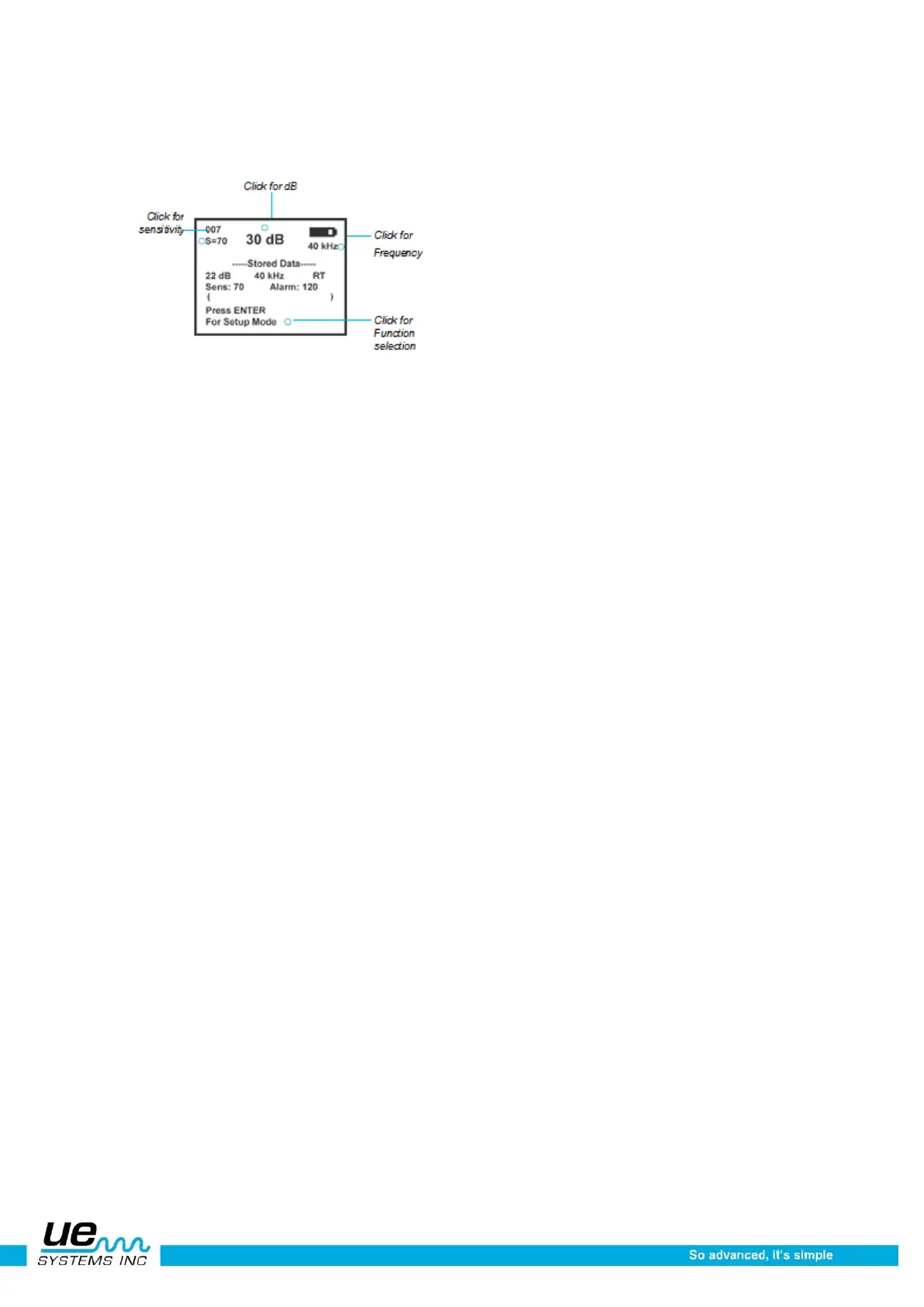
Moving around the Display Panel is easy. Basically three clicks (presses) of the Sensitivity Control
Dial will move the cursor on the Display Panel to three key spots: the Decibel Indicator, the Frequen-
cy Indicator, and the Function Selection Indicator.
 Loading...