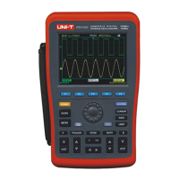
6. The power supply indicator:
● The Oscilloscope is powered by the battery;
The Oscilloscope is powered by DC power adaptor.
7. The marker for ground reference point for displayed waveforms;
8.1×: indicates probe attenuation factor for the channel is 1×;
9. The readout for main timebase setting;
10. “Connected to PC” icon;
11. Readout for the current vertical scale factor;
12. Waveform Invert Indicator that indicates that the waveform is reversely displayed;
13. Position readout from the channel reference marker to the horizontal line on the screen.
4.4 Resetting the Oscilloscope
To reset the Oscilloscope to the default, do the following:
1. Press SHIFT button, “shift” icon displays on the upper right corner of the screen;
2. Press UTILITY button and four options shows on the bottom display;
3. Press F2 button to select the default setup. Then the Oscilloscope is set to the default settings;
Note: Pressing up arrow button can also set the Oscilloscope to the default when powering on.
Figure 4-2 Default Setup
The Default setup is as follows:
 Loading...