Connections
The system is based on a bus communications protocol (requires the
thermostats unique ID to be registered to the controller), utilising
daisy chain, direct or star topology connections. This allows serial
and parallel connections, making wiring and connection of
thermostats and system devices much easier than connecting one
thermostat per connection terminal.
The wide array of connection possibilities presented with this
communications protocol can be combined in any way best suited for
the current system.
Thermostats and actuators
• Thermostat #01 controls actuator channels 01a, 01b, 02a and
02b with the help of an option.
• Thermostat #03 controls actuator channels 03 to 05 with the
help of an option.
• Thermostat #06 controls actuator channels 06 and 07.
• Thermostat #08 controls actuator channels 08 to 10 with the
help of an option.
• Thermostat #11 controls actuator channels 11 and 12.
System devices
Note
If registering a public thermostat with various functions as
a system device, the thermostat only acts as a remote
unit. It does not control the room temperature in the room
where it is placed.
Note
System devices can only be registered to the master
room controller.
Note
The room controller will time out after about 10 minutes
of inactivity and revert to normal operation. The timer will
be reset when a button is pressed or if a device has been
registered to it.
Note
Sub room controllers can only be registered to the
master room controller.
Note
If a room controller has been connected to a
communication module, disconnect the communication
module and restore it to sub room controller state by
factory reset.
Existing sub room controllers in the system must then
either, reset system device channel 01, or register to
another master room controller.
• Multiple room controllers
Multiple Uponor Smatrix room controllers can be linked together
by assigning one room controller to be master and the rest to be
sub room controllers.
The master room controller is assigned by connecting it to the
communication module (only one room controller can be master
in the system), and it can control up to three sub room
controllers. Sub room controllers are assigned when registered
(in order) to the master room controller.
• Public thermostat T-143 with various functions (options B and
C).
Option A
• External temperature sensor.
• Floor temperature sensor.
Option B
• Outdoor temperature sensor.
Option C
• External temperature sensor for heating/cooling switch.
• Comfort/ECO mode switch.This option disables the
Comfort/ECO option in the GPI.
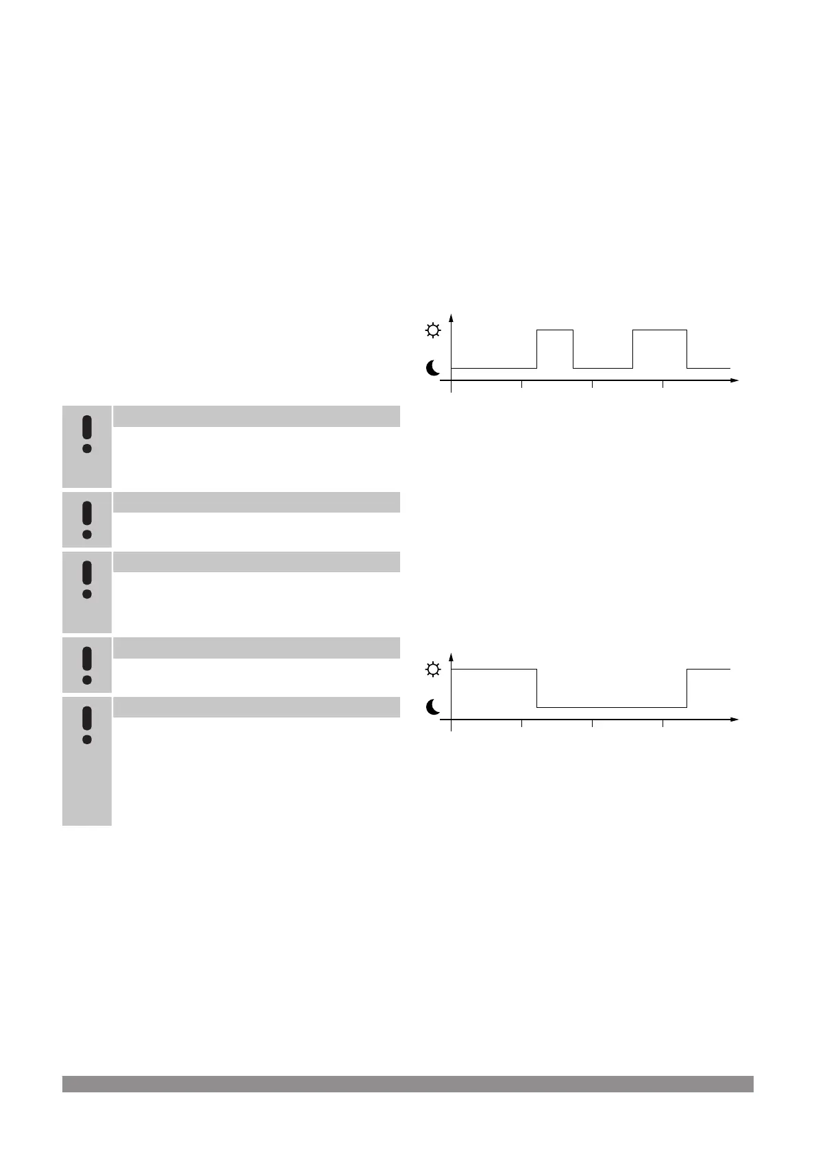
Schedules
Programmable schedules can, during heating and/or cooling, switch
between Comfort and ECO mode. See example below.
0 h 00 24 h 0018 h 0012 h 006 h 00
DI0000012
Figure 1. Schedule 1
Other rooms can, depending on system setup, simultaneously switch
between Comfort and ECO mode according to their own programmed
schedules.
This requires one or more of the following:
• Uponor Smatrix PULSE app (requires communication module
connected to Uponor cloud services)
The app allows for system wide, or individually programmed,
schedules for the rooms in the system. Any other devices with its
own programmed schedules are overridden and its menus
hidden.
• Uponor Smatrix Wave T-148
The thermostat is in control of its own room, with restrictions
stated above, regarding the Uponor Smatrix PULSE.
0 h 00 24 h 0018 h 0012 h 006 h 00
DI0000013
Figure 2. Schedule 2
Even if programmed schedules exist in the system, some rooms may
still operate without any scheduling. These rooms will operate in
constant Comfort mode and is not affected by the programming of
other rooms.
Room sensor T-141:
• Set the value using the Uponor Smatrix PULSE app (requires
communication module).
Public thermostat T-143:
• Set the switch on its back to comfort mode only.
Flush thermostat T-144:
• Set the switch behind the dial to comfort mode only.
Standard thermostat T-145:
• Set the switch on its back to comfort mode only.
Digital thermostats T-146 and T-149:
• Set the ECO setback value in menu 03 to 0.
Uponor Smatrix Base PULSE
|
Installation and operation manual
|
17