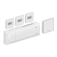
15.3 Uponor Smatrix Base PULSE room controller layout
D F F K
C G H L MI G GJEBA
CD0000152
Item Description
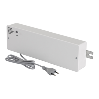
A Transformer, 230 V AC 50 Hz power module
B Fuse (T5 F3.15AL 250 V)
C Optional inputs and outputs (pump and boiler management)
D Channel registration buttons
E LEDs for channels 01 – 06
F Quick connectors for actuators
G Bus connection terminals
H System bus connection terminals
I Power LED
J Uponor Smatrix Base Slave Module M-242 (optional slave module)
K LEDs for channels 07 – 12
L Uponor Smatrix Base Star Module M-243 (optional star module)
M End cap
15.4 Wiring diagram
Uponor Smatrix Base PULSE room controller
WD0000022
GPI
RELAY 2 (BOILER)
RELAY 1
(PUMP)
GPI 1
GPI
GPI 2
GPI 3
A B + - A B + - A B + - A B - A B -
92
|
Uponor Smatrix Base PULSE
|
Installation and operation manual