ENGLISH
- 39 -
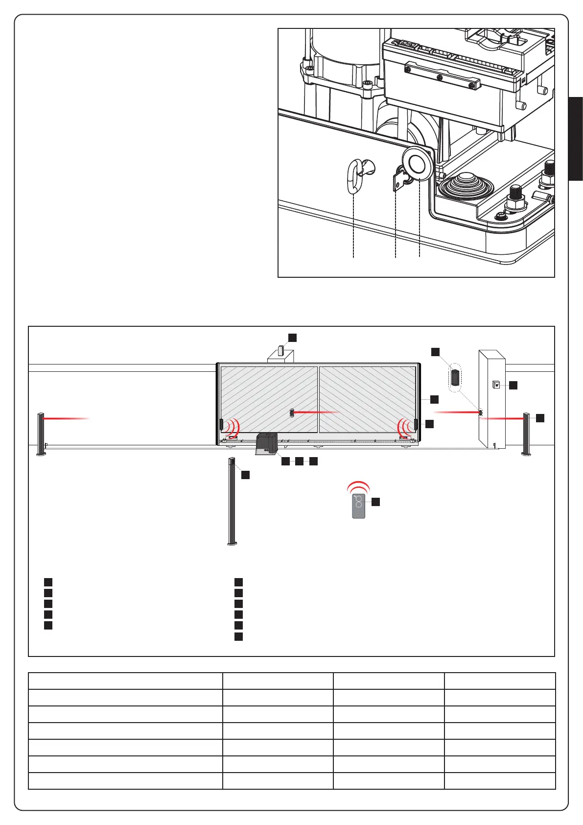
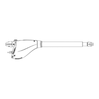
3.5 - MOTOR OVERRIDING SYSTEM
In case of absence of current, the gate can be released by
operating on the motor:
1. Open the hatch of the lock J in front of the motor
2. Insert the key K in the lock and turn clockwise to open
the hatch of the release on the side
3. Insert the key L into the hole and turn clockwise until
reached the limit switch
4. At this point you can manually move the gate
To restore the automation, proceed as follows:
1. Bring the gate to the fully closed position
2. turn the key L anticlockwise until reached the limit
switch, then draw it out
3. turn the key K anticlockwise closing the hatch of the
lock, then draw it out
4. Close the lock with the hatch J
3.6 - INSTALLATION LAYOUT
1 3 E
5
4
A
B
F
D
2
C
LENGTH OF THE CABLE < 10 metres from 10 to 20 metres from 20 to 30 metres
Power supply 230V 3G x 1,5 mm
2
3G x 1,5 mm
2
3G x 2,5 mm
2
Photocells (TX) 2 x 0,5 mm
2
2 x 0,5 mm
2
2 x 0,5 mm
2
Key switch 4 x 0,5 mm
2
4 x 0,5 mm
2
4 x 0,5 mm
2
Photocells (RX) 2 x 0,5 mm
2
2 x 0,5 mm
2
2 x 0,5 mm
2
Flashing light 2 x 1,5 mm
2
2 x 1,5 mm
2
2 x 1,5 mm
2
Antenna (integrated into the flashing light) RG174 RG174 RG174
A
B
C
D
E
F
1
2
3
4
5
Key switch
Pillar photocells
Pillar-mounted digital radio switch
Safety edges
WES-ADI module (via radio management of edges)
WES sensors
Motor
Transmitter
Receiving module
Photocells
Flashing light
COMPONENTS ADDITIONAL ACCESSORIES
L K J