EasyManuals Logo

Vacon 100 Installation Manual

Vacon 100
156 pages
To Next Page IconTo Next Page
To Previous Page IconTo Previous Page
Page #123 background imageLoading...
Page #123 background image
I
L
I
L*110%
1 min 9 min
I
t
I
L*110%
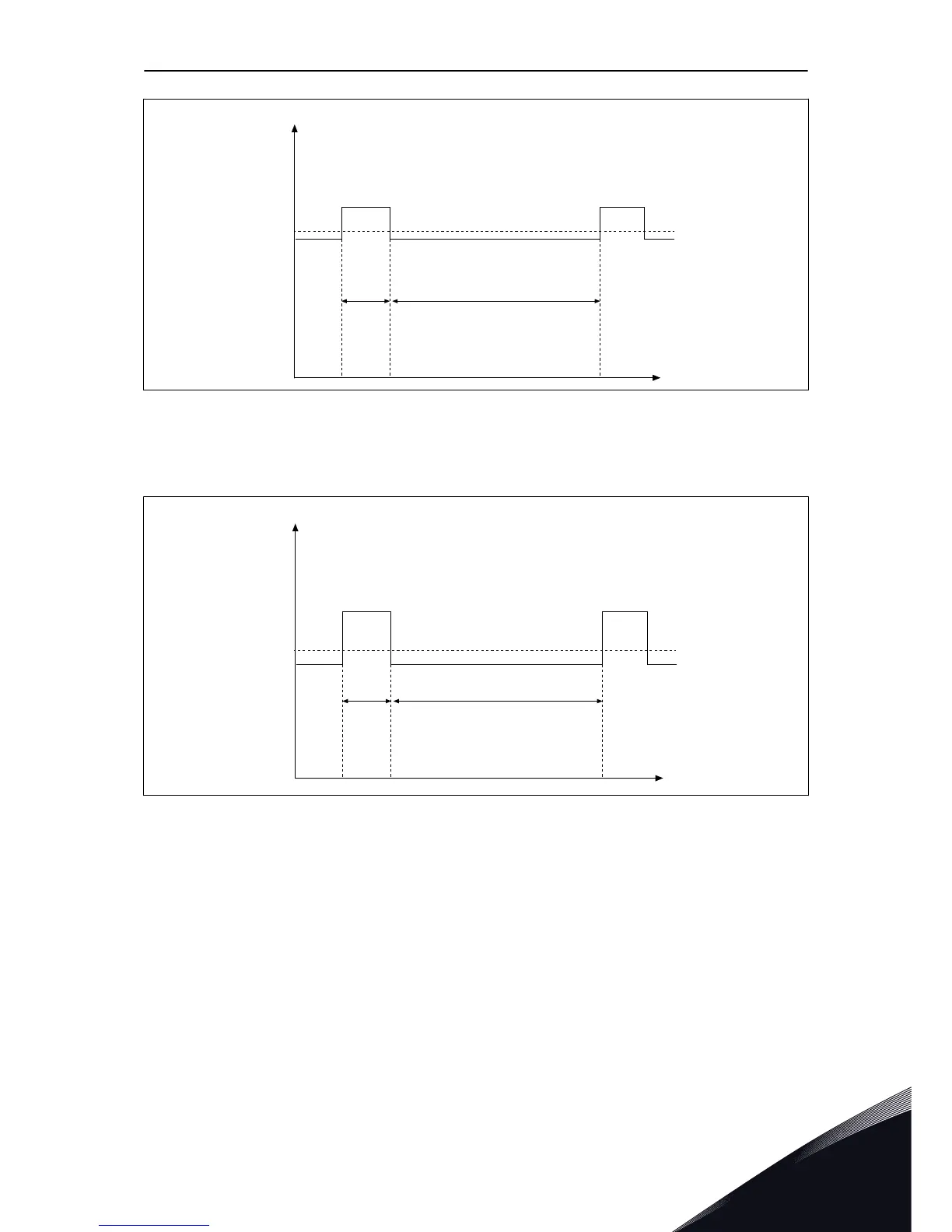
Fig. 46: Low overload
The high overload means that if 150% of the continuous current (I
H
) is necessary for 1
minute each 10 minutes, the remaining 9 minutes must be approximately 92% of I
H
or less.
This is to make sure that the output current is not more than I
H
during the duty cycle.
I
H
I
H*150%
1 min 9 min
I
H*150%
I
t
Fig. 47: High overload
For more information, refer to the standard IEC61800-2 (IEC:1998).
8.1.6 BRAKE RESISTOR RATINGS
Make sure that the resistance is higher than the set minimum resistance. The power
handling capacity must be sufficient for the application.
TECHNICAL DATA, VACON® 100 VACON · 123
24-HOUR SUPPORT +358 (0)201 212 575 · EMAIL: VACON@VACON.COM
8

Table of Contents

Other manuals for Vacon 100

Questions and Answers:

Question and Answer IconNeed help?

Do you have a question about the Vacon 100 and is the answer not in the manual?

Vacon 100 Specifications

General IconGeneral
Product typeAC Drive
Enclosure classIP20
EMC filterBuilt-in
Power0.25 kW - 5.5 kW
Cooling methodFan
Braking chopperOptional

Related product manuals