I. A DIP switch for the signal selection of
Analogue Input 1
J. The status indicator of the Ethernet
connection
K. A fan (only in IP54 of MR4 and of MR5)
L. The battery for the RTC
M. The location and the default position of
the Safe Torque Off (STO) jumper
When you receive the AC drive, the control unit contains the standard control interface. If you
included special options in your order, the AC drive will be as in your order. On the next
pages, you will find information on the terminals and general wiring examples.
It is possible to use the drive with an external power source with these properties: +24 VDC
±10%, minimum 1000 mA. Connect the external power source to terminal 30. This voltage is
sufficient to keep the control unit on and for you to set the parameters. The measurements
of the main circuit (for example, the DC link voltage, and the unit temperature) are not
available when the drive is not connected to mains.
The status LED of the drive shows the status of the drive. The status LED is located in the
control panel, below the keypad, and it can show 5 different statuses.
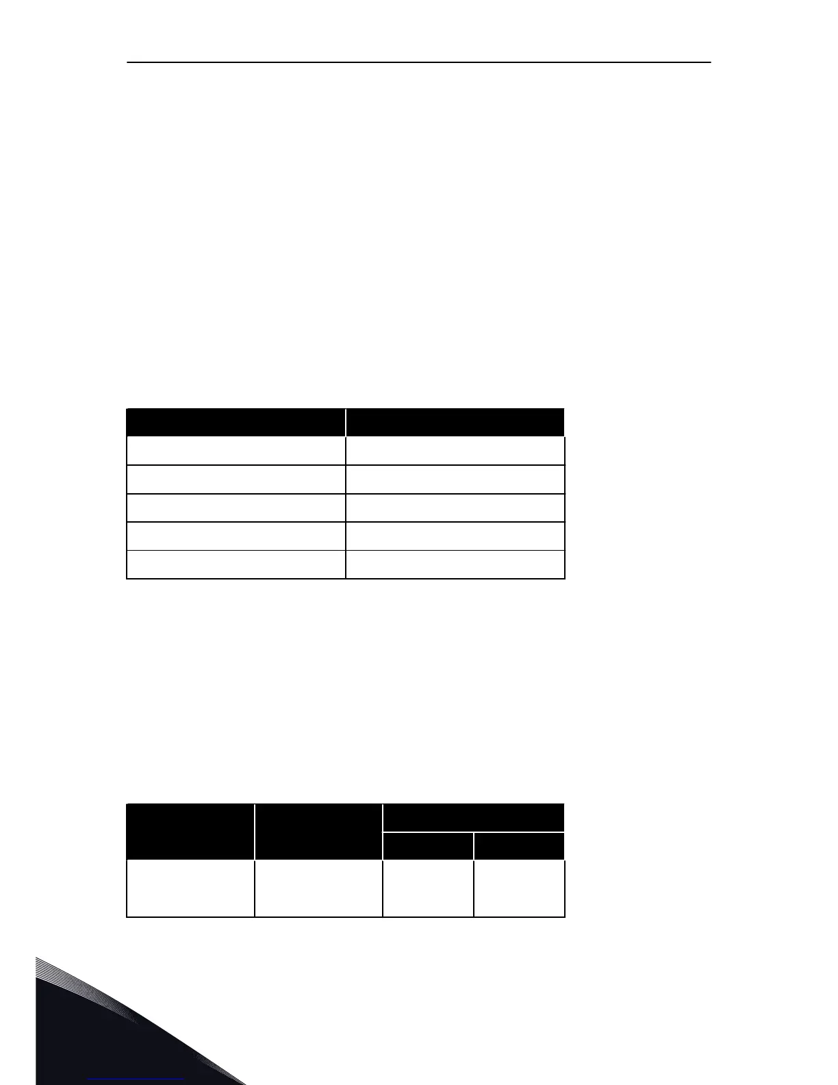
Table 27: The statuses of the status LED of the drive
Colour of the LED light Status of the drive
Blinking slowly Ready
Green Run
Red Fault
Orange Alarm
Blinking fast Downloading software
6.2 CONTROL UNIT CABLING
The standard I/O board has 22 fixed control terminals and 8 relay board terminals. You can
see the standard connections of the control unit and the descriptions of signals in Fig. 39.
6.2.1 SELECTION OF THE CONTROL CABLES
The control cables must be a minimum of 0.5 mm
2
screened multicore cables. See more on
the cable types in Table 15 The selection of the correct cable. The terminal wires must be a
maximum of 2.5 mm
2
for the relay board terminals and other terminals.
Table 28: The tightening torques of the control cables
The terminal The terminal screw The tightening torque
Nm lb-in.
All the terminals of
the I/O board and the
relay board
M3 0.5 4.5
VACON · 90 CONTROL UNIT
6
TEL. +358 (0)201 2121 · FAX +358 (0)201 212 205

 Loading...


