6 CONTROL UNIT
6.1 CONTROL UNIT COMPONENTS
The control unit of the AC drive contains the standard boards and the option boards. The
option boards are connected to the slots of the control board (see 6.4 Installation of option
boards).
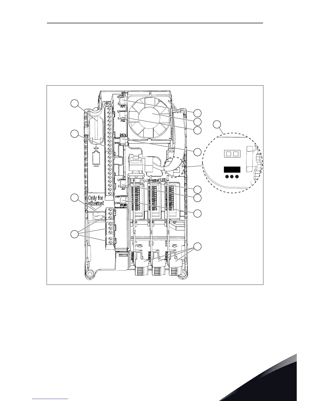
Fig. 38: The components of the control unit
A. The control terminals for the standard
I/O connections
B. The Ethernet connection
C. The relay board terminals for 3 relay
outputs or 2 relay outputs and a
thermistor
D. The option boards
E. A DIP switch for the RS485 bus
termination
F. A DIP switch for the signal selection of
Analogue Output
G. A DIP switch for the isolation of the
digital inputs from ground
H. A DIP switch for the signal selection of
Analogue Input 2
CONTROL UNIT VACON · 89
24-HOUR SUPPORT +358 (0)201 212 575 · EMAIL: VACON@VACON.COM
6

 Loading...


