11 TECHNICAL DATA ON CONTROL CONNECTIONS
11.1 TECHNICAL DATA ON CONTROL CONNECTIONS
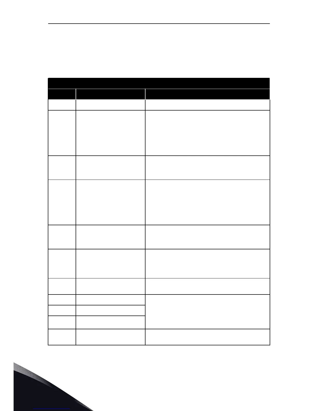
Table 53: The standard I/O board
Standard I/O board
Terminal Signal Technical information
1 Reference output +10 V, +3%, maximum current: 10 mA
2
Analogue input, voltage or cur-
rent
Analogue input channel 1
0...+10 V (Ri = 200 kΩ)
4-20 mA (Ri =250 Ω)
Resolution 0.1 %, accuracy ±1 %
Selection V/mA with dip-switches (see chapter 6.2.2.1 Selec-
tion of terminal functions with DIP switches)
3
Analogue input common (cur-
rent)
Differential input if not connected to ground
Allows ±20 V common mode voltage to GND
4
Analogue input, voltage or cur-
rent
Analogue input channel 2
Default: 4-20 mA (Ri =250 Ω)
0-10 V (Ri=200 kΩ)
Resolution 0.1 %, accuracy ±1 %
Selection V/mA with dip-switches (see chapter 6.2.2.1 Selec-
tion of terminal functions with DIP switches)
5
Analogue input common (cur-
rent)
Differential input if not connected to ground
Allows ±20 V common mode voltage to GND
6 24 V aux. voltage
+24 V, ±10%, max volt. ripple < 100 mVrms
max. 250 mA
Short-circuit protected
7 I/O ground
Ground for reference and controls (connected internally to
frame ground through 1 MΩ)
8 Digital input 1
Positive or negative logic
Ri = min. 5 kΩ
0-5 V = 0
15-30 V = 1
9 Digital input 2
10 Digital input 3
11 Common A for DIN1-DIN6
Digital inputs can be disconnected from ground, see chapter
6.2.2.2 Isolation of digital inputs from ground.
VACON · 152 TECHNICAL DATA ON CONTROL CONNECTIONS
11
TEL. +358 (0)201 2121 · FAX +358 (0)201 212 205

 Loading...


