User's Guide _______________________________________________________________________
102
_____________________________________________________ M210296en-A
9611-004
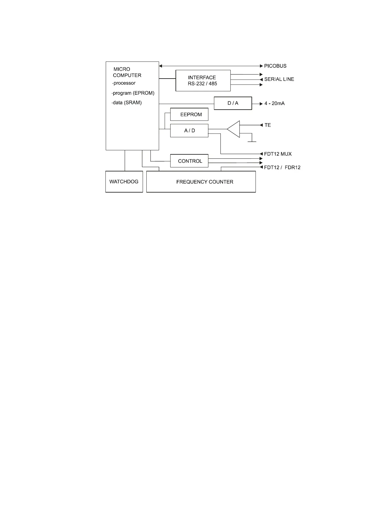
Figure 26 FDP12 Control Unit Block Diagram
The controller is based on an Intel® 8031 microprocessor. Besides
data acquisition and internal controlling, the FDP12 takes care of
communication through the RS-232 serial port. The alternative
RS-485 interface allows a simple method for multiple FD12P Weather
Sensors to communicate on the same line. The PICOBUS interface
facilitates a connection to a number of Vaisala peripheral units. The
memory includes a 512-kbit EEPROM for program code and a 256-
kbit static RAM for data and working parameters. For configurable
parameters, there is a serial non-volatile EEPROM.
The special frequency measurement circuitry measures the optical
signal that is converted into frequency in the Receiver Unit FDR12.
The watchdog circuit monitors the +5 V level as well as the system
operation creating a hardware reset when necessary. For internal
monitoring of analog signals, the CPU board contains an 8-bit A/D
converter. Along with Mux-signals from the crossarm, the lens
heating current and the ambient temperature are sampled. The Control
unit further includes an accurate, 12-bit D/A converter, which can be
configured for two-wire, 4 to 20 mA-current output.