User's Guide _______________________________________________________________________
98
______________________________________________________ M210296en-A
An extra photodiode measures the light scattered backwards from the
lens, other objects, or contaminants. This signal as well as several
internal signals are monitored via MUX-line.
The CPU board supplies only one voltage Vb = 10 - 13 V for both the
transmitter and receiver. This is used for heating the lenses, for the
transmitter LED heating and for producing both +5 V digital and
+15 V analog supplies. The +15 V supply is located on the FDT12B
board.
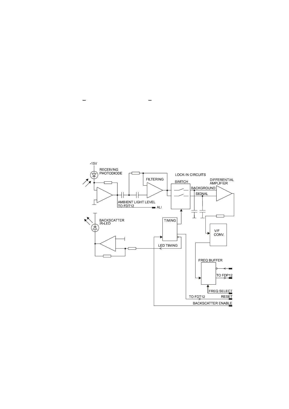
FDR12 Receiver Unit
The Receiver Unit consists of a light receiver, preamplifier, voltage to
frequency converter, backscatter measurement light source LED, and
some control and timing electronics.
9611-003
Figure 23 FDR12 Receiver Block Diagram
The receiving PIN photodiode senses the transmitted light pulses
scattered from the aerosol particles. The signal voltage is filtered and
detected by a phase-sensitive, lock-in amplifier synchronized with the
transmitter.