Chapter 5 _______________________________________________________ Functional Description
VAISALA ________________________________________________________________________ 97
9611-002
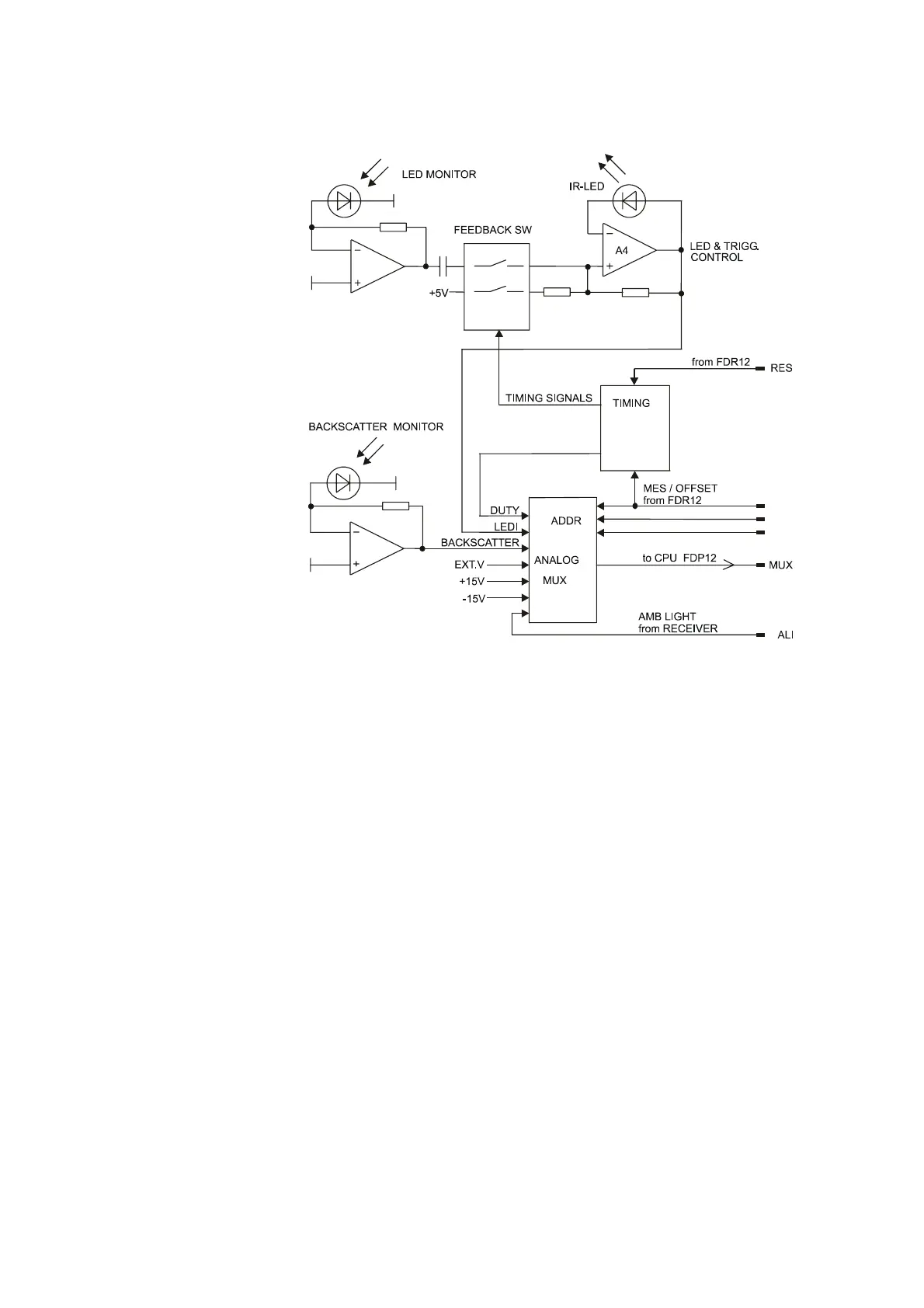
Figure 22 FDT12B Transmitter Block Diagram
The transmitter unit electronics pulses the IR-LED at a frequency of
2.3 kHz. One PIN-photodiode monitors the transmitted light intensity.
The transmit level measurement is used to automatically keep the
LED's intensity at a preset value. The "LEDI" feedback voltage is
channeled through the analog multiplexer to the CPU for monitoring.
The feedback loop compensates for temperature and aging effects of
the light-emitting diode. On the other hand, the active compensation
slightly accelerates the LED aging. For this reason, the initial LED
current is set to a value, which guarantees several years of
maintenance-free operation.
A reset pulse (RES) from the FDR12 Receiver synchronizes the IR-
LED timing with the receiver's lock-in amplifier. The CPU can also
delay the transmitter firing for a special out-of-phase measurement.
This feature is used in measuring the internal noise level (offset) of the
circuitry.