Appendix B ___________________________________________ Jumper Settings and Internal Wiring
VAISALA _______________________________________________________________________ 149
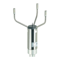
CPU Board
Table 35 CPU Board Jumpers
Jumpers Description
X2 Memory selection 1-2 for 27256, 2-3 for 27512
X5 Watchdog ON 1-2, reset 2-3
X7 PICOBUS
TM
powering
X11 Not in use
X13 Lens heating 1-2, on 2-3 with on/off driver
Table 36 CPU Board Connectors
Connectors Description
X3 PICOBUS (for DRI21 interface board)
X14 Temperature sensor (FDE12)
X15 To transducer crossarm (transmitter/receiver)
X16
Not in use!
X17 Supply voltage, pin 4: 10-12 VDC, pin 6: GND
X18 RS-232 connector pin 1: GND, pin 2: RxD, pin 3: TxD (for
remote and maintenance use)
X19 RS-232 control signals (for DMX21 or other options)
X20 Analog current output (sinking type)
X21 RS-485 (alternative use to RS-232)
DC-Regulator
Table 37 DC-regulator Connectors
Connectors Description
X1 Pin 1, 3: output for hood heaters, (pin 3: alternative status
relay output)
X2 Pin 1, 2: power input 18 ... 26 V (electronics), pin 3, 4: power
input 20 ... 24 VAC/4A for hood heaters, (pin 4: alternative
status relay input)
X3 DC output connector pin 6: GND, pin 4: +11..12 V
DRI21 Interface Board
Table 38 DRI21 Interface Board Jumpers
Jumpers Description
X3 PICOBUS address selection