Chapter 3 ________________________________________________________________ Installation
VAISALA ________________________________________________________________________ 55
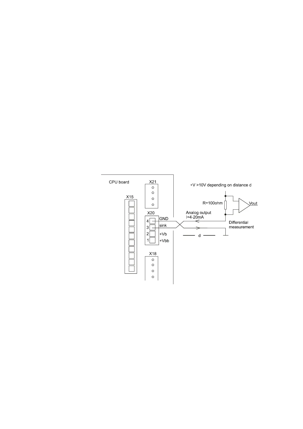
Analog Transmission
For 4-20 mA analog visibility measurement only two wires are
needed. Do the following:
1. Connect the voltage supply either from remote or internal supply
(from +V
b
= 12 V or +V
bb
= 23 V) to resistor R (for example,
100 ohm).
2. Connect the signal wire to screw connector X20 pin 3 "sink" at
the CPU board. In the drawing, a remote voltage supply is used
and the return signal is wired from pin 4 "gnd". See Figure 20
below.
For more information of the analog output port functioning and
configuring, see section Analog Output Commands on page 91.
9607-007
Figure 20 Analog Current Loop Option
Connecting the Maintenance Terminal
Any computer equipped with a terminal emulation software or a
VT100 compatible terminal with the RS-232 serial interface can be
used as a maintenance terminal for the FD12P. The optional
maintenance cable provides a 9-pin D-connector for the computer and
a 3-pin connector for the FD12P.