User's Guide _______________________________________________________________________
46
______________________________________________________ M210296en-A
0110-184
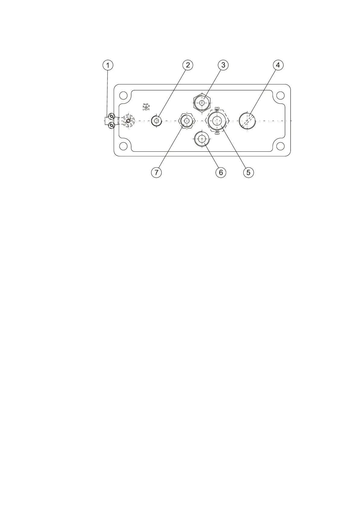
Figure 13 Electronics Enclosure Feedthroughs
The following numbers refer to Figure 13 above:
1 = Grounding
2 = DTS14 cable feedthrough
3 = Temperature sensor (TE)
4 = Cap (Pg 13.5) of optional opening for the LM11
background luminance meter
5 = Main power cable
6 = FDC115 transducer cable feedthrough
7 = Standard communication cable feedthrough
Communication Cable EMC-shielding
The electronics enclosure has one cable outlet for a cable diameter
from Ø7 to Ø10 mm, which is reserved for a signal or modem cable.
Although the shielding of the cable may be just grounded after cable
inlet, an efficient procedure against RF-interference requires special
care. Ground the cable gland to keep EMI levels within specifications.
For a proper RF-grounding of any jacketed cable, the instructions are
the following:
1. Lead the signal cable through the cable inlet. If the field cable is
thicker than 10 mm, use a separate signal junction box. See
Figure 14 on page 47.
2. Strip 80 mm of the cable sheath leaving approximately 40 mm
of the shield.