1002
Model Code Page
66. Air suspension of front axle
1. 8. 2000
660 26200--8950
1. 11. 1998
M20 (8+8 pcs), 380 Nm
s=30 (S=10, option)
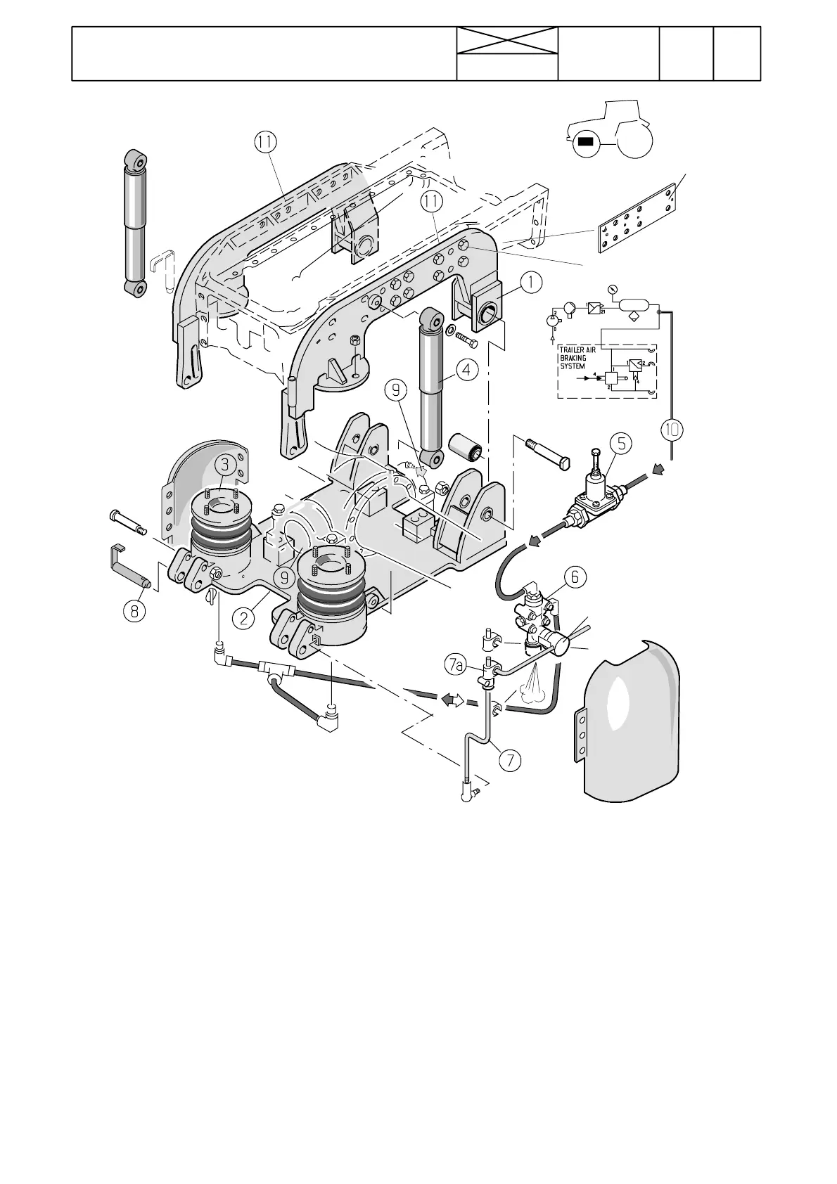
Picture 2. Air suspension system for front axle
1. Joint pin bracket
2. Bottom plate
3. Rubber bellows
4. Shock absorber
5. Overflow valve (if the tractor has the trailer air brakes, the overflow valve ensures enough high pressure in the brakes even
though there is a leakage in the suspension system).
6. Levelling valve
7. Feeler linkage of the levelling valve
7a. Adjusting piece of linkage
8. Locking pin (the suspension ca n be l ocked by fitting the lock pin into the round holes. If the holes do not align, turn th e
levelling valve linkage to align the holes).
9. Grease nipples of axle brackets. The nipple of the foremost bracket is placed under the bracket (greasing at every 250
running hours)
10. Pressure air intake from reservoir (symbols in picture, see picture 7 on page 510/6).
11. Spacer plates between the frames (plate thickness depends on the front mounted implement)
Note! The front axle loading is 350 kg greater than on t he tractor without the air sus pension. The max. permissible axle load-
ings are the same as for the industrial front axle and standard front axle.