Floor hatch
763
Model Code Page
441. Quick ---shift gear
6100--8400 441 3
15. 5. 1993
8. 11. 1990
2. Fitting quick---shift gear
A . A t t a c h i n g 2 --- s t e p q u i c k --- s h i f t g e a r t o
reverse shuttle
Important! 3---step quick shift gear (Delta Powershift), see
under code 444.
1. Fit the centring ring, large o---ring and small o---ring round
the oil bore between the quick---shift gear and the reverse
shuttle.
Note! If necessary, o---rings can be fixed with a little grease.
2. Plac e the quick---shift gear onto the reverse shuttle input
shaft.
3. Tighten the quick---shift gear fixing bolts to a torque of 45
Nm.
4. Connect the oil pipes and the solenoid valve lead to the
q u ic k --- sh if t gea r.
Note! Check and change, if necessary, the needle bearing
and oil seal inside the input shaft front end. The seal can be
fitted with drift ETV 892 180.
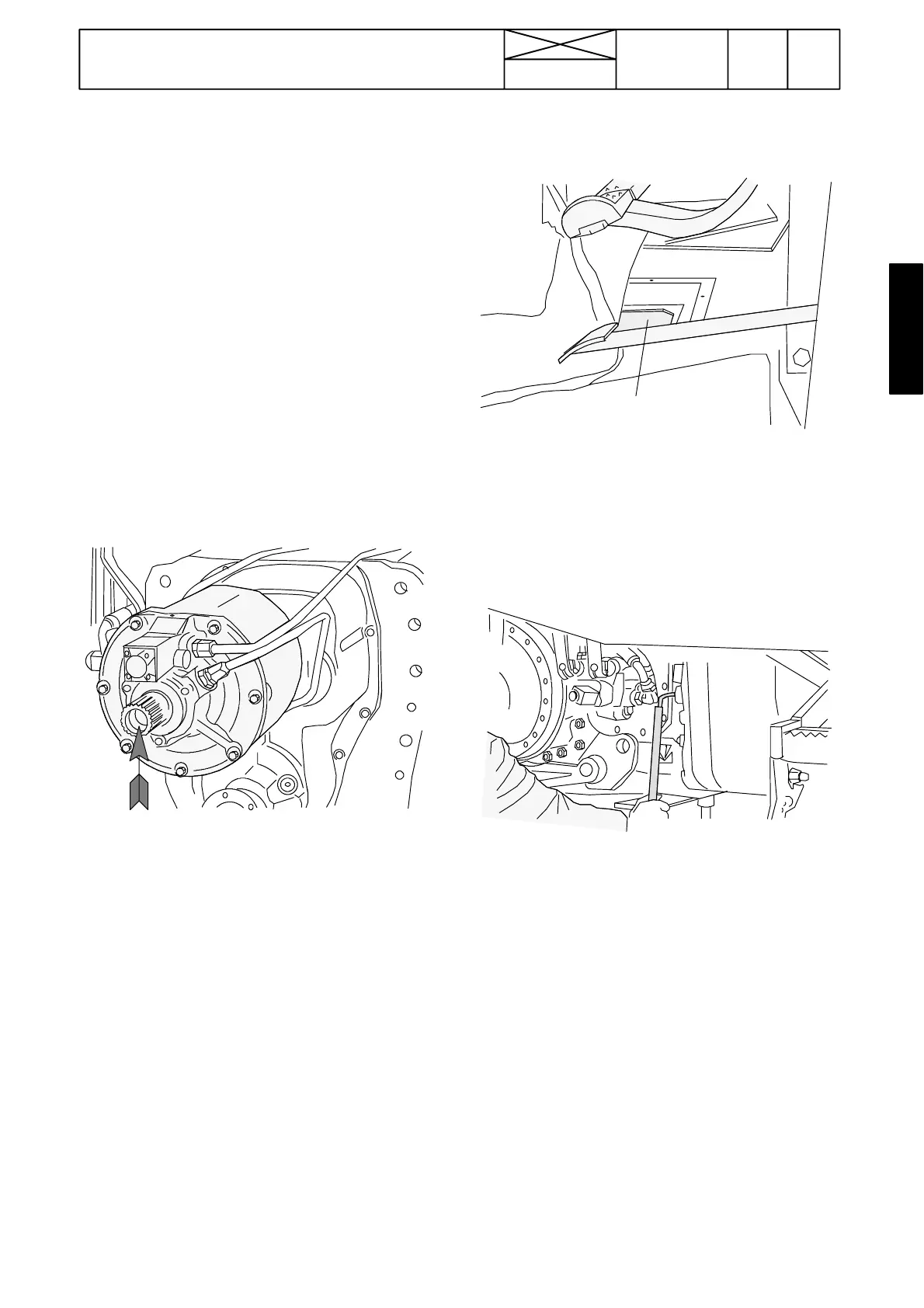
5. Carefully push the pump drive shaft through the input shaft
fully home. Place the c onnecting sleeve onto the quick---shift
gear input shaft.
B. Assembling tractor frame betwee n
g e a r b o x --- f u e l t a n k .
1. Open the floor hatch
2.Pushthefrontframeagainstthegearboxandguidethe
connec ting sleeve through the floor hatch.
Note! Rotate, if necessary, the flywheel for easier engage-
ment of the pump drive shaft front end splines. Also guide the
2---step quick---shift gear solenoid valve wire into place.
3. Push the frame parts against each other so that the guide
pins and studs engage with their holes. Tighten the frame joint
bolts (nuts onto studs 300 Nm, hexagonal socket---head
screws 125 Nm). Remove the supports under the tractor.
Important! If the tractor has Delta Powershift, guide the pro-
peller shaft rear end onto the 4WD output shaft splines.
4. Connect the hoses to the hydraulic lift controlvalve and also
the hoses to the pressure filter (on the RH side).
5. Connect the oil cooler pipes to the servo valve block (on the
LH side of the gearbox).