658
Model Code Page
41. Clutch
6000--8750 411 10
1. 1. 1995
1. 1. 1994
4. Adjusting and repair instru ction
for clutch releas e mechanism of
cable type, 659478---
Note! This new mechanism is fitted on all 6000---8400 trac-
tors with effect from tractor ser. no. 659478.
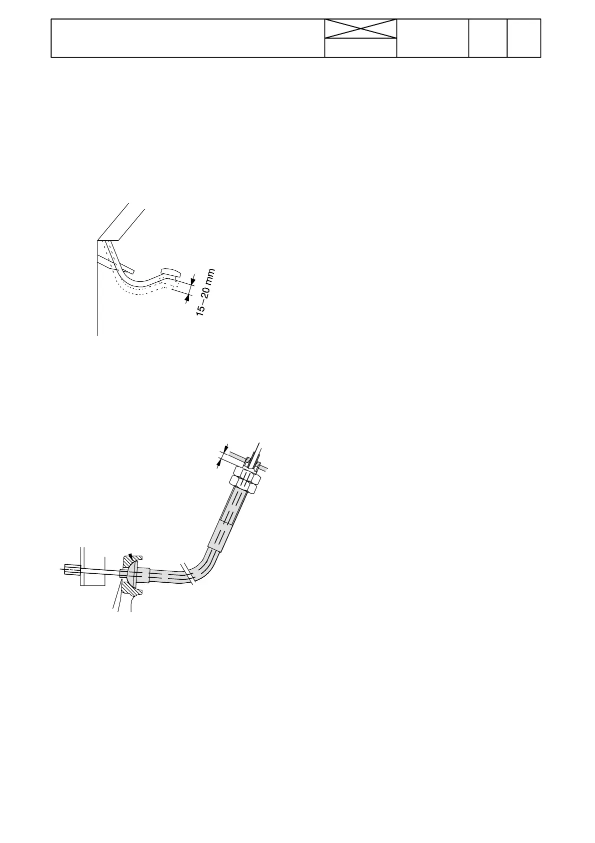
A. Adjusting clutch pedal free travel.
6181---87
2. The free travel at the pedal should be 10---15 mm.Thefree
travel is difficult to verified by depresseing the pedal.
3. If the free travel is not correct, adjust it with an adjusting
sleeve at the cabl e lead---in point in the cab front wall.
3mm
4. When the pedal is in the upper position, the distance bet-
ween the cab wall and the adjusting sleeve should be 3 mm,
which corresponds to the correct free movement.
Note! The distance is adjusted by turning the sleeve and by
moving the cable until the free travel between the sleeve and
the cab front wall is correct. If the pedal does not return to the
upper position, it may be necessary to adjust the clutch servo,
see page 410/5.
B. Clutch repairs
The tractor frame is split and assembled according to instruc-
tions 411 1A and D. The clutch assembly is the same as
earlier.
The release bearing cannot be removed as described in instr.
C on page 411/3. The easiest way to remove the bearing is
to place a suitable drift against the bearing support tube and
by pulling out the bearing with an extractor.
C. Changing release cable
The cable can be changed without splitting the tractor. There
is an access hole on the tractor frame through which the
clutch end of the cable can be disconnected from the upper
end of the release lever. After changing the cable, the clutch
pedal free travel should be adjusted.
Note! The clutch cable has been strengthened with effect
from tractor ser. no. 665081. Thenewcableisexchangeable
with the earlier cable after renewing the adjusting nut. On Hi---
Trol models the cableupper end fork should also be changed.
The Spare Part Centre dispatches only the new cables. All
earlier type cables should be returned t o the tractor factory.
Check the function of the c able via the access hole.
If the cable does not function correctly, split the tractor at the
clutch and check the position and alignment of the clutc h
lever and the cable support. The support groove must must
be in line with the clutch lever, clutch shaft centre and clutch
lever attachment centre line.
If necessary, remove the support and reweld it into place.
Check the function of the clutch lever lower end ball joint.
Assure that the cup springs are fitted correctly. Nut tightening:
first fully home and upscrew it 3/4 or 1/4 turn (depending on
the tractor ser no). Reassemble the tractor.
Check again the function of the cable. Test---drive the tractor
and checkthe adjustment of the cable and readjust, if necess-
ary