131
Model Code Page
37. Autocontrol 5
1. 8. 2000
370 13
6250--8950
1. 9. 2002
J. Te sting proportional valves (P1---P6) in the test mode in AC 5
NOTE! Corresponding tests in AC 5.2, see page 371/9B.
Note! When the pro portional valves are tested, all solenoid outputs are connected automatically unenergised. Note! The PTO
proportional valve canno t be tested in the test mode in AC 5, but the solenoid is checked by measuring the resistance value.
Hint! E.g. value P4 1.8 means, that the forward direction proportional valve takes max. current of 1,8 A (in the test mode).
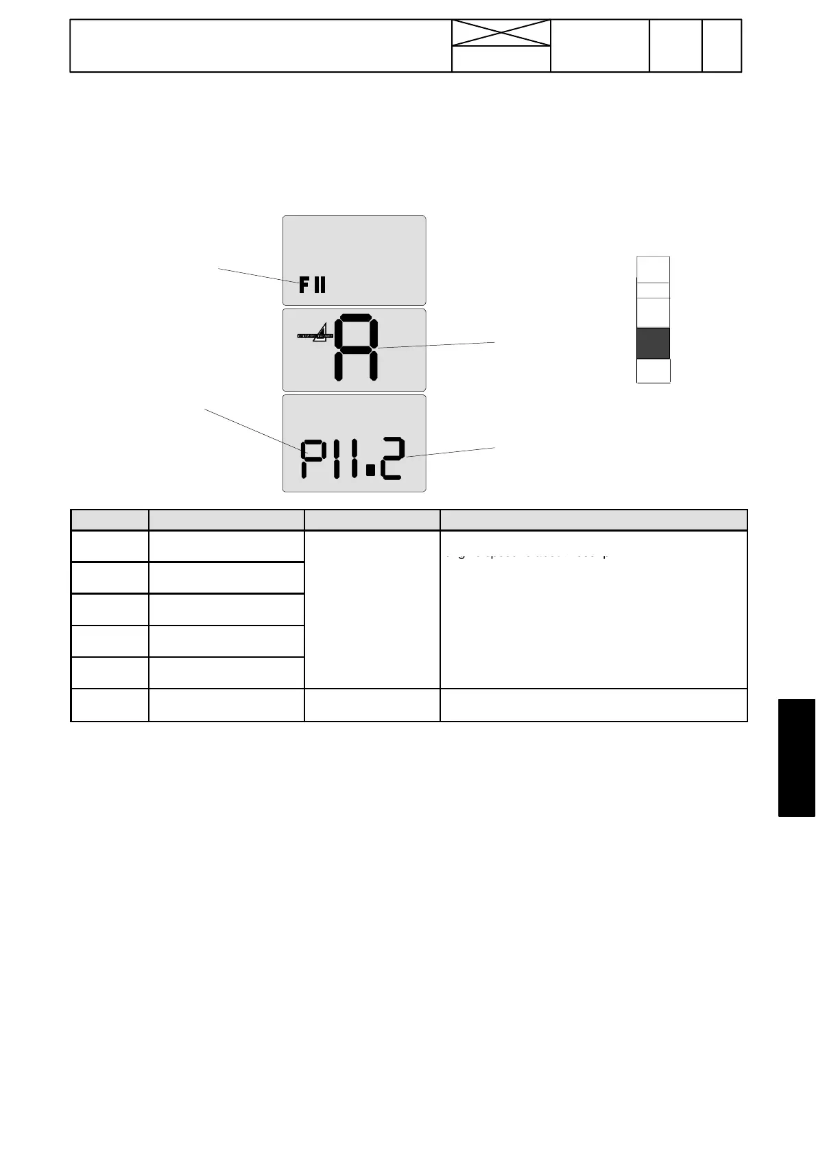
Example:
P1=DPS
proportional
valve no 1
(C1)
Module A=AC 5
1.2=value within given
limits (1,2 A)
FII=test
mode
symbol
F
A
d
P
C
OUTPUT NAME VALUE (activated) DESCRIPTION
P1 (Y4) D P S --- s o l e n o i d Y 4 ( C 1 ) . Activate the test mode and start the engine. Set the
engine speed to about 1000 rpm.
P2 (Y6) D P S --- s o l e n o i d Y 6 ( C 2 ) .
1,1---1,9 *
P3 (Y17) D P S --- s o l e n o i d Y 1 7 ( C 3 ) .
1,1---2,2
Proportional valve is activated by stepping the desired
solenoid and by pushing the pre---programming but-
-
P4 (Y11) Forwards solenoid Y11.
(program versions
53, 65)
.
-
ting values.
P5 (Y12) Rearwards solenoid Y12.
--- If HI=short circuit or valve takes too high current.
--- If LO=wire damage
P6 (Y2) PTO solenoid Y2
In AC 5: Canno t be tested in test mode. Measure re-
sistance, see page 370/21.
* Although the current value is between the limiting values, can fault codes P101...P109 appear. In that case the AC5 ---con-
trol unit must be re---programmed with a new main program file ( versions 53 or 65) and the suitable parameter file (see page
370/24G). Newest program versions all ow a little higher current values, because the higher curre nt taken by a cold solenoid
coul d cause a fault code.
--- If one of the values in the diplay deviates from the given values, measure the solenoid resistance on the connector X13 pins
or direct on the valve pins. Measure so that the pins do not slacken (see instr. C on page 370/21). If the resistance is correct,
but the display reading is faulty, the fault lies in the wires.
Measure also the supply voltage o f the control unit while t he engine is running (1500 rpm). Correct value is 12 V ---14,8 V.
--- If the solenoid resistance was faulty, the solenoid is damaged and should be changed. When the propor tional valve o r the
solenoid is changed, the valve indexes must be checked (see page 370---24D).
If above mentioned points are OK, faulty current value can be caused by a defect AC5 / 5.2 control unit A1.
Note! Resistance measures and dio de checks, see instr. 4C on page 370/21.
Important! Be careful not to mix up the proportio nal valves and normal solenoid valves during repair work.
WARNING! The proportional valves have a pin for a manual use, which MUST NOT be manipulated: the tractor may sudden-
ly star t to move, or the pin can become trapped and can cause later damage to e.g. multi---disc cl utches. That is why it must
always be checked after the repair work (before engine start), that the proportional valve spools are in the outer positions i.e.
almost flush with the valve body (if not, remove the valve and press the spool so that the “manual pins” rises).