130
Model Code Page
37. Autocontrol 5
1. 8. 2000
370 12
6250--8950
1. 9. 2002
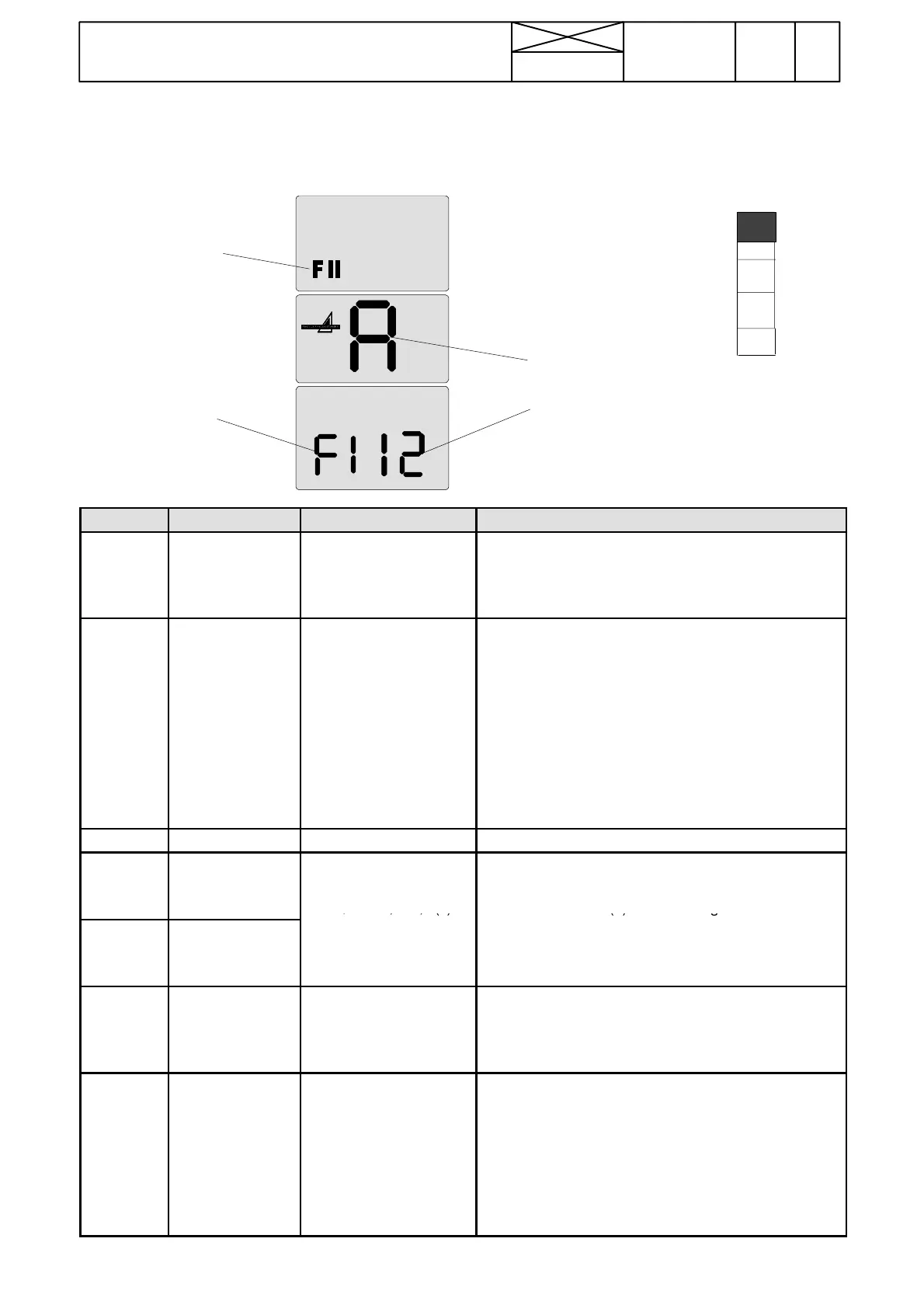
I . Te s t i n g R P M --- s e n s o r s ( F 1 --- F 7 ) i n t h e t e s t m o d e i n A C 5
NOTE! Corresponding tests in AC 5.2, see page 371/9A.
Note! If the display shows e.g. F1 51, it means the engine rpm sensor frequency of 5100 Hz (value x100=Hertz number).
F1=engine
RPM sen-
sor
Module A=AC 5
12=possible sig-
nal value at engi-
ne speed of 2000
r/min
Example:
FII=test
mode
symbol
F
A
d
P
C
INPUT NAME VALUES DESCRIPTION
F1 (B11) Engine rpm sensor 1000 r/min=5,7---6,3
1500 r/min=8 ---10
2000 r/min=11 ---13
Set the engine revs to 1000 r/min and compare the value
with the given values in the LH side col umn. Raise the
revs to 1500 and 2000 r/min and compare the reading. If
one o f the values is no t within the given limits, check the
sensor, see instr. D on page 370/22.
F2 (B6) Gearbox speed
sensor
1000 r/min=0,6 ---0,8 (50
km/h)
1500 r/min=1,1 ---1,3 (50
km/h)
2000 r/min=1,4 ---1,8 (50
km/h)
1000 r/min=0,5 ---0,7 (40
km/h)
1500 r/min=0,8 ---1,1 (40
km/h)
2000 r/min=1,1 ---1,5 (40
km/h)
Set the engine revs to 1000 r/min, engage gear M1 and
drive the tractor forwards. Compare the reading with the
given value. Test also at 1500 and 2000 rpm engine revs.
Ifthevaluesdiffer,seeinstr. D sivulla 370/22.
F3 Reserve
F4 (B12) Shuttle output
speed (upper sen-
sor)
1000 r/min=1,8 ---2,1 (F)
1500 r/min=2,9 ---3,1 (F)
2000 r/min=3,8 ---4,2 (F)
Set the gears in neutral. Set the engine revs to 1000
r/min. Engage forward direction (F) and compare the
value with t he given value. Make the same check also in
the reverse direction (R). Raise the engine revs to 1500
F5 (B13) Shuttle output
speed (lower sen-
sor)
1000 r/min=1,9 ---2,2 (R)
1500 r/min=3,0 ---3,2 (R)
2000 r/min=3,9 ---4,3 (R)
and 2000 r/min and measure again in both directions.
Compare the reading with the given values. If one of the
values deviates, carry out a comparing measurement,
check the senso r according to inst r. D on page 370/22.
F6 (B7) PTO speed sensor 540=1,7 ---2,0
540E=2,2 ---2,5
1000=3,0---3,3
540E=2,2---2,5 (8350Hi)
1000E=3,7---3,9 (8350Hi)
Engage PTO. Set the engine revs to 1000 r/min. Compare
the values with the given values. If the values deviate,
check the senso r acording to instr. D on page 370/22.
F7
(B12, B13)
Direction informa-
tion
F=1
R=2
Set the gears in neutral. Set the engine revs to 800 r/min.
Engage the forward direction (F) and raise slowly the
engine revs up to max. The reading must be 1 and must
remainthesameduringthewholetest.Engagereverse
direction (R) and repeat the same measurement. The rea-
ding must be 2 during the whole measurement. If one of
the direction readings does not function (value is faulty or
it changes when engine revs varie), but F4 and F5 values
are correct, the AC 5/5.2 control unit A1 may be damaged
and should be changed.
NOTE! If the measured values deviate from the above given values, check first the driver detection switch and its wiring in the
seat.