69
Model Code Page
21. Engine
1. 8. 2000
6000--8950 215 1
1. 10. 1999
Lubricating system (Op no
215)
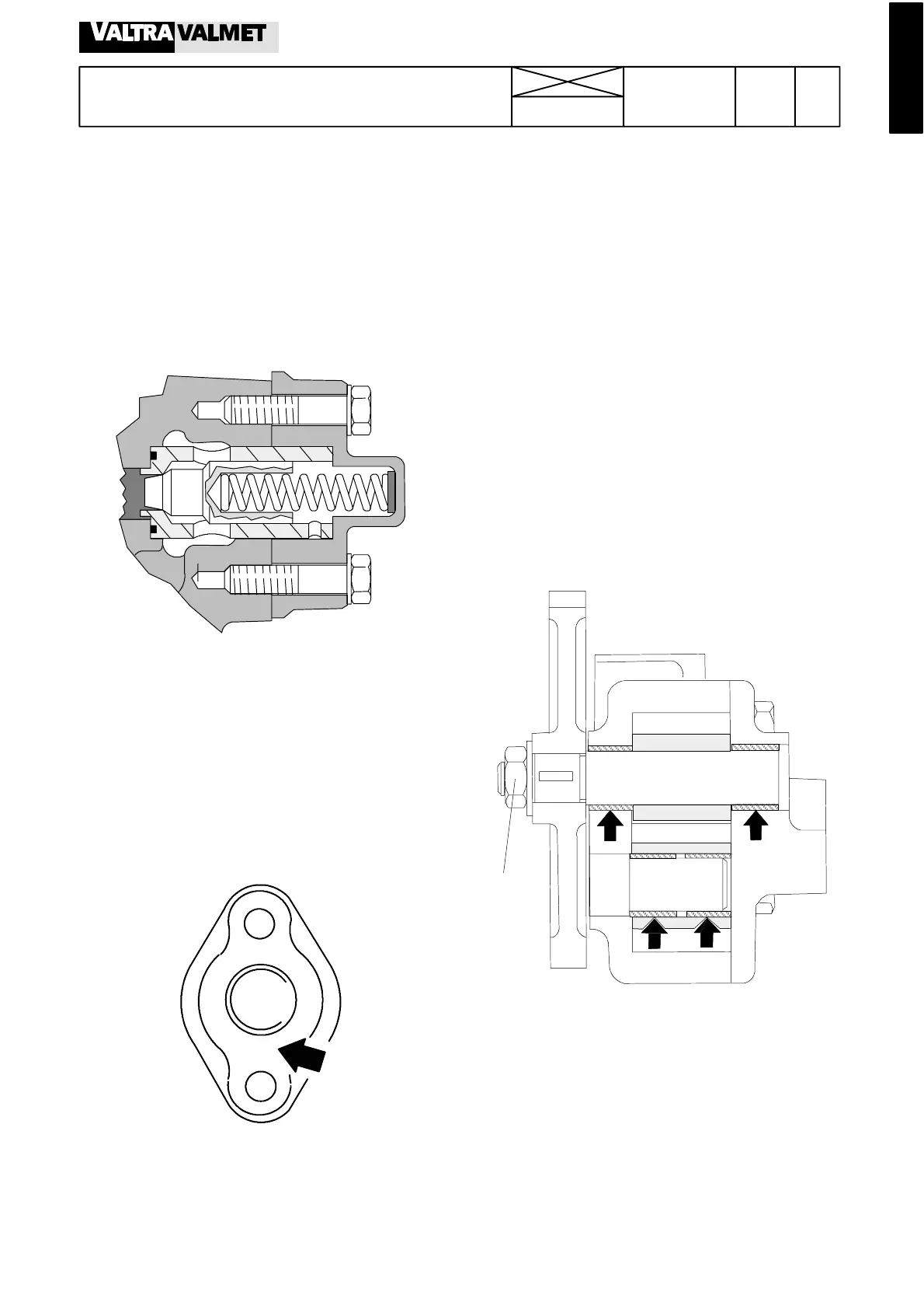
A. Re c onditioning of oil relie f v alv e for
lubricating oil pressure
Note! The latest relief valve, see page 215/4.
If the engine lubricating oilpressure is insufficient or if it varies,
the relief valve should be checked after first chec king the oil
level.
1. Remove the cover over the valve (13 mm) and spring. Take
care of the washer between the cover and spring. Remove the
valve insert together with the valve cone and ensure that the
o---ring is also removed.
2. Clean the parts and check t hat the valve cone slides freely
in the insert and that the sealing surface are undamaged. Mi-
nor damage can be adjusted, but in general, damaged parts
should be changed. Scrape off any remains of the gasket.
3. Assemble the valve with a new o---ring and insert it in the
cylinder block. Place the washer and spring in the cover and
fititwithanewgasket.
4. Note that the relief valve cover is not symmetrical. The
greater distance between the spring housing and bolt should
be turned downwards.
NOTE! The relief valve spring is shorter on tractors, which
have the cooling nozzles for the pistons (8400, 8450, 8550,
8750). The valve cone has been changed for a new one in the
tractor production.
B. Re moving and dismantling lubric ati ng
oil pump
Note! Concerning the latest type oil pump in 6---cyl. engines
from engine no. J7034 incl., see page 215/5.
1. Remove the engine (or detach the oil sump, see page
219/1).
2. Remove the oil pump suction and pressure pipe.
3. Remove the oil pump together with any shims between the
pump and the cylinder block.
4. Remove the pump cover and the gasket. Remove the gear
on the dead axle.
5. Clamp the pump gear across the teeth in a vice fitt e d with
softjaws, and loosen the drive gear nut. Knock the gear wheel
off by hitting the end of the shaft with a soft hammer. Pull out
the drive shaft---gear wheel
6. Clean the parts and check for wear and other damage.
Compare with the specifications.Change damaged parts and
all seals.
60 Nm
7. On 620---engines the bearing points are provided with sep-
arate bearing bushings. If You changethe bushings,machine
them to dimension of 18,000 ---18, 018 after fitting.
Note! With effect from engine ser. no. C1474 (320), C1328
(420) and C1133 (620) the engine lubricating oil pump has
been changed.
The fitting between gear and shaft has been changed from
cylindrical type with key to a taper without key.
As a spare part the complete new pump is exchangeablewith
the earlier pump. The new drive gear and the shaft can be
fitted in pairs on the earlier pump.