133
Model Code Page
23. Cooling system
1. 1. 1995
6000--8750 231 3
1. 9. 1992
5. Remove the circlip in the pump body. Press the shaft
together with bearings in the direction of the fan. Use e.g. a
hydraulic press. Support the pump body so that the bearings
have enough space for releasing.
6. Tap out axial and shaft s eals using a drift. Clean the parts
and inspect their condition. Replace faulty or worn parts with
new ones.
N.B. If the pump bearings have to be changed, use a recondi-
tioning kit. This kit also contains all seals (see Parts Cata-
logue).
7. Drive in the new shaft seal in the housing using a suitable
drift. Put the bearings and the intermediate sleeve onto the
shaft. Grease bearings with heat---resistant ball bearing
grease. Fit the shaft and the bearings in such a way that the
pressing force is not transmitted by the bearing balls. Fit the
circlip for the bearing.
8.Fittheshaftseal,seeheading B paragraph 8.
120 Nm
0,8---1,2mm
620/634
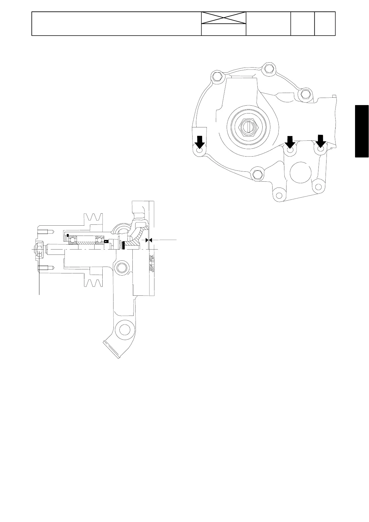
9. Press the impellerinto position while, at thesame time, sup-
porting the shaft at the other end. The mounting depth of the
impeller is 0,8 ---1,2 mm (see figure above). Make sure that
theshaftcanrotatefreely.
10. Fit the belt pulley and tighten its attaching bolt to a torque
of 120 Nm.
11. Fit the rear plate using new seals. Use guide pins (ø 8,5
mm) in the holes shown with arrows in the picture above.
D. Quality requirements of coolant
ThecoolantusedmustmeetthestandardsASTM
D3306---86a or BS 6580:1985.
--- Mixing proportion should be 40---60 % of ethyls---glycol
based coolant and the rest water. The best ratio is 50/50 %.
--- In warm climates the 30 % mixture ratio gives enough good
protection against corrosion.
--- Water used should be clean and soft water i.e. that it does
not include metals and their salts.
--- Check the coolant frost resistance every now and then.
Change the coolant every other year. Never use just water as
a coolant.