100
Model Code Page
32. ACB / ACD power lift
1. 9. 2002
8250--8150
321 8B
1. 11. 1998
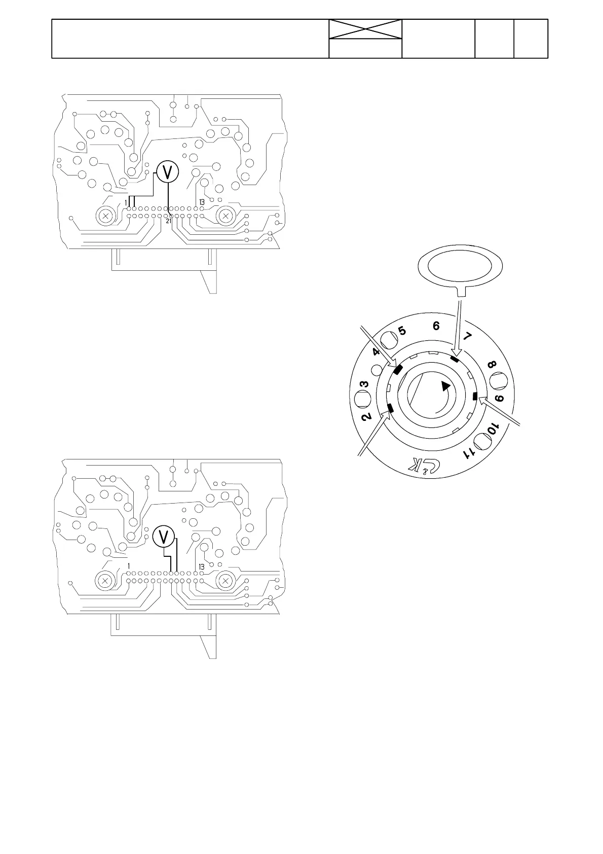
5. Checking DBC selector S12E
Picture e) Measure voltage between pins 21 and 1 (DBC)
with two selector positions:
Position Pin 1
O F F 2 , 0 --- 2 , 4 V
DBC switched o n 0
Note! If the measured values in points 2 --- 5 deviate from the
given values, the fault lies in the switch panel circuit card
which should be changed.
6. Checking lift/stop/lowering switch S10E
Picture f. Measure voltage between pins 8 and 9 with all
three switch positions:
Position Pin 9
Lowering 2,4---2,8 V
Middle position (Stop) 3,5 ---4,0 V
Transport position 4,9--- 5,4 V
Note! If the measured values deviate from the given values,
check the switch connector. If the values are further incorrect,
the fault lies in the circuit card which should be changed.
G. Changing switch panel, ACB/ACD
Note! If the voltage measurements show that the switch panel
is defective the panel must be replaced as a complete unit as
follows:
1. Remove the DPS circuit card support plate and the card
from the ACD switch panel.
1. Detach the switch panel from the bracket by removing se-
lector knobs and by unscrewing ring nuts. Remove the dust
seals.
2. Detach the switch panel connector so that the panel can be
removed.
3. Fit onto new selectors washers with lugs. These washers
limit selector positions. Before fitting the washers turn every
selector anti ---clockwise as far as possible to their extreme
positions. After this fit washers so that the lugs engage in the
holes given below:
--- lowering speed selector; hole 9.
--- transport height selector; hole 9.
--- draft control selector; hole 7.
--- DBC without slip control; hole 2.
--- DBC with slip control; hole 4.
4. Ensure by rotating the selectors, that the lowering speed
and transport height selectors have 9 positions, draft control
selector 7 position and DBC selector 2 (DBC) or 4 (DBC +slip
control) positions.
4. Connect the connector to the new switch panel. Fit the dust
covers (no 317 204 20) onto the washers and fasten the circuit
card to the switch panel with the ring nuts (under the nuts lock-
ing washers JE 9423).
5. Fit the knobs and fasten the DPS circuit card. Attach the se-
lector panel onto the lever console.