X13
X28
482
Model Code Page
37. Autocontrol 5 / 5.2
1. 8. 2000
370 22
6250--8950
1. 10. 1999
F1
F4
F5
F6
F2
B6
B7
B11
B12
B13
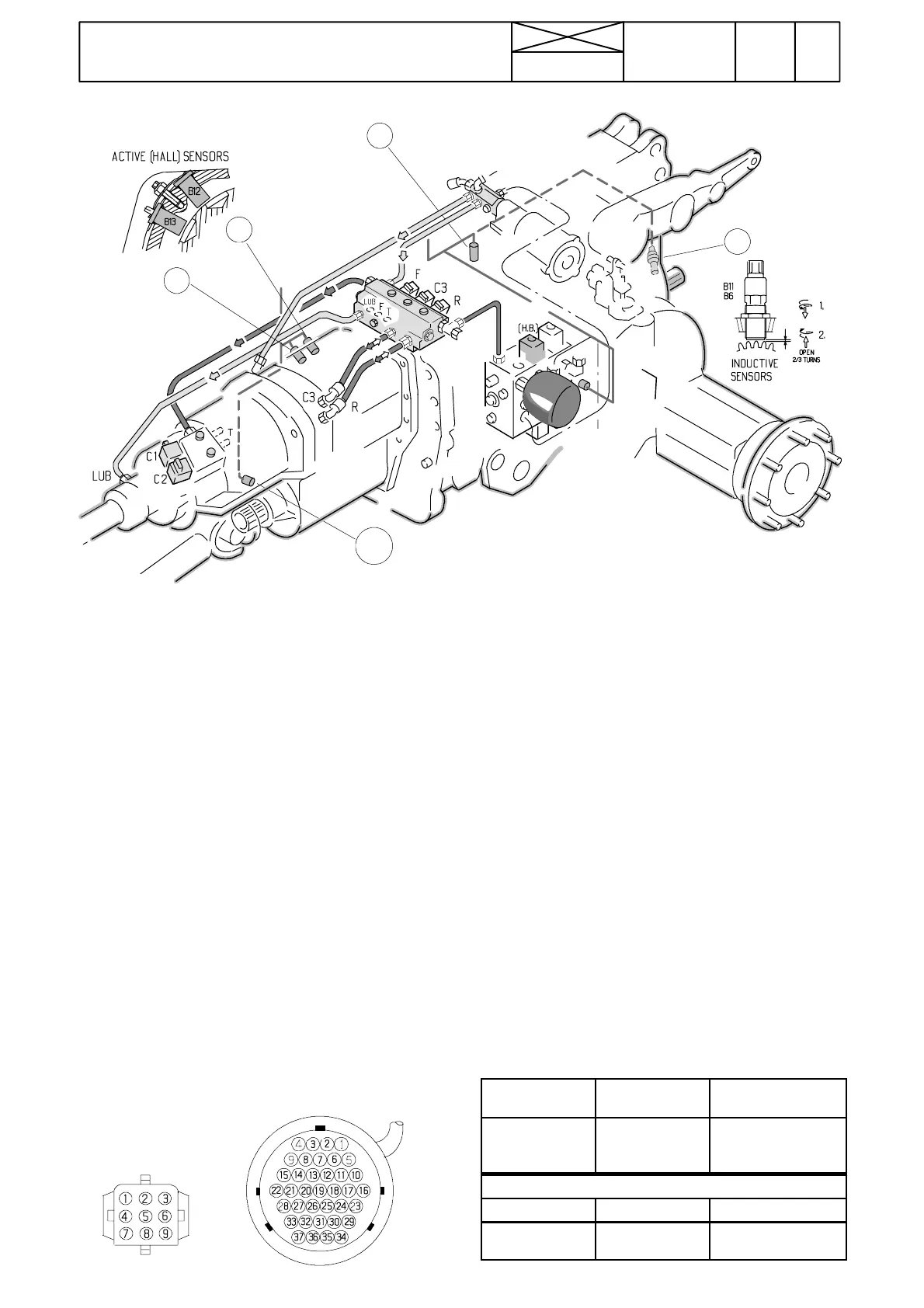
D. Rotation speed sensors, AC 5 and 5.2
Note! If you doubt that one speed sensor is faulty, carry out
the checking of frequency outputs, see table c on page
370/12.
The fault codes can show possible faults in the rotation
speed sensors. Fault code list, see page 370/6 (AC 5) or
pages 371/5 and 6 (AC 5.2).
F1=engine speed sensor B11
F2=gearbox speed sensor B6
F4=shuttle speed sensor B12 (upper), order no on wire.
F5=shuttle speed sensor B13 (lower), not order no.
F6=PTO speed sensor B7
1. If in the test mode one sensor functioned faulty, measure
the resistance of the sensor. The resistance can be
measured from the wire loom connector X13. If the resis-
tance is infinitive, it should be measured from the sensor
pins so that possible breaks can be verified.
2. The resistance of the shuttle sensors F4 and F5 cannot
be measured. These sensors are tested in the test mode
FII. Check first sensor fuse (F22, AC 5 only) and measure
sensor supply voltage (=battery voltage) in connector X28
(see table below)
Note! The gearbox speed sensor is accessible after split-
ting the tractor frame. The other sensors are accessible
without splitting the tractor. The engine speed sensor is
situating under the cab on the gearbox. The shuttle speed
sensorsareaccessiblefromunderthecabontheRHside
of the tractor when a cover is removed.
3. If the sensor resistance is correct, check the sensor wires
and connectors. If the resistance was incorrect, the sensor
is changed.
4. Fitting and adjustment of sensors F1, F2 and F6 is done
in the same way as for corresponding sensors on the AC IV
unit, see pages 351/2---3.
5.TheshuttlesensorsF4 and F5 cannot be adjusted, but
they are pushed into place and locked with a locking plate.
Note! The sensors must be fitted correctly: F4 up (marked),
and F5 down. Check the sensors in the test mode, point F7.
6. If the wires and sensors are OK, but malfunctions exist, it
is possible that the control unit is faulty.
RESISTANCE MEASUREMENTS
PINS (X13)
SENSOR RESISTANCE
+10---+30˚C
14<>6
15<>6
19<>6
B11
B6
B7
1000---1100 ohms
Supply voltage measurements (B12, B13)
Pins (X28) Sensor Voltage
3<>1
9><7
B12
B13
Battery voltage
--- ” ---