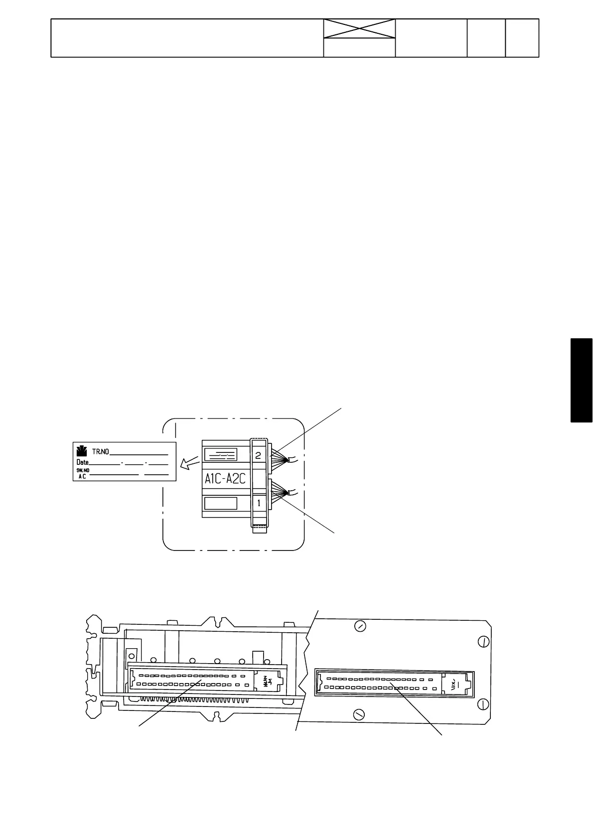
A1C
A2C
Upper connector A2C
Lower connector A1C
Picture 5. The ECS is placed in the lever console
and is accessible after removing the console side
panel.
Picture 6.RearsideoftheECS
V oltage and resistance measurements can be done from the pins of connectors A1C and A2C. The pins have
been numbered.
Supply voltage can be measured from connector A2C: Earth A2C/1. Supply voltage A2C/2, A2C/21 and A2C/25
(current must be switched on)
393
Model Code Page
35. Autocontrol IV
15. 5. 1996
6600E
8100E-- 8750E
350 9
1. 1. 1995
Wiring and connectors
See picture 4 on previous page.
1. Display unit with connector X11C.
2. Central unit (ECS, in the lever console).
3. Slip control (+buzzer)
4. PTO emergency stop socket
5. Implement socket
6. ECS wiring loom
7. Cab wiring loom
8. Engine wiring loom
9. Rear socket wiring loom
10. Power lift wiring loom
11. If the ECS is damaged, the PTO automatics can be over-
ridden by disconnecting wire nr 314 (lilac) from the emerg-
ency stop socket (in the lever console) and then by connect-
ing free wire nr 113 (yellow) inplace of the lilac wire. The PTO
can now be controlled manually with the switch S25 in the
PTO lever knob. The emergency stop functions also with this
connection but not the slip control.
Note! With effect from spring ---96 a new connector X4C has
been fitted for the sensors in the front part of the tractor. This
connector is in the engine compartment on the RH side.
Note! With effect from ser. no. F17107 the PTO control system
has been modified. In this new system the PTO has a relay
control (compare AC II and AC 2.1).