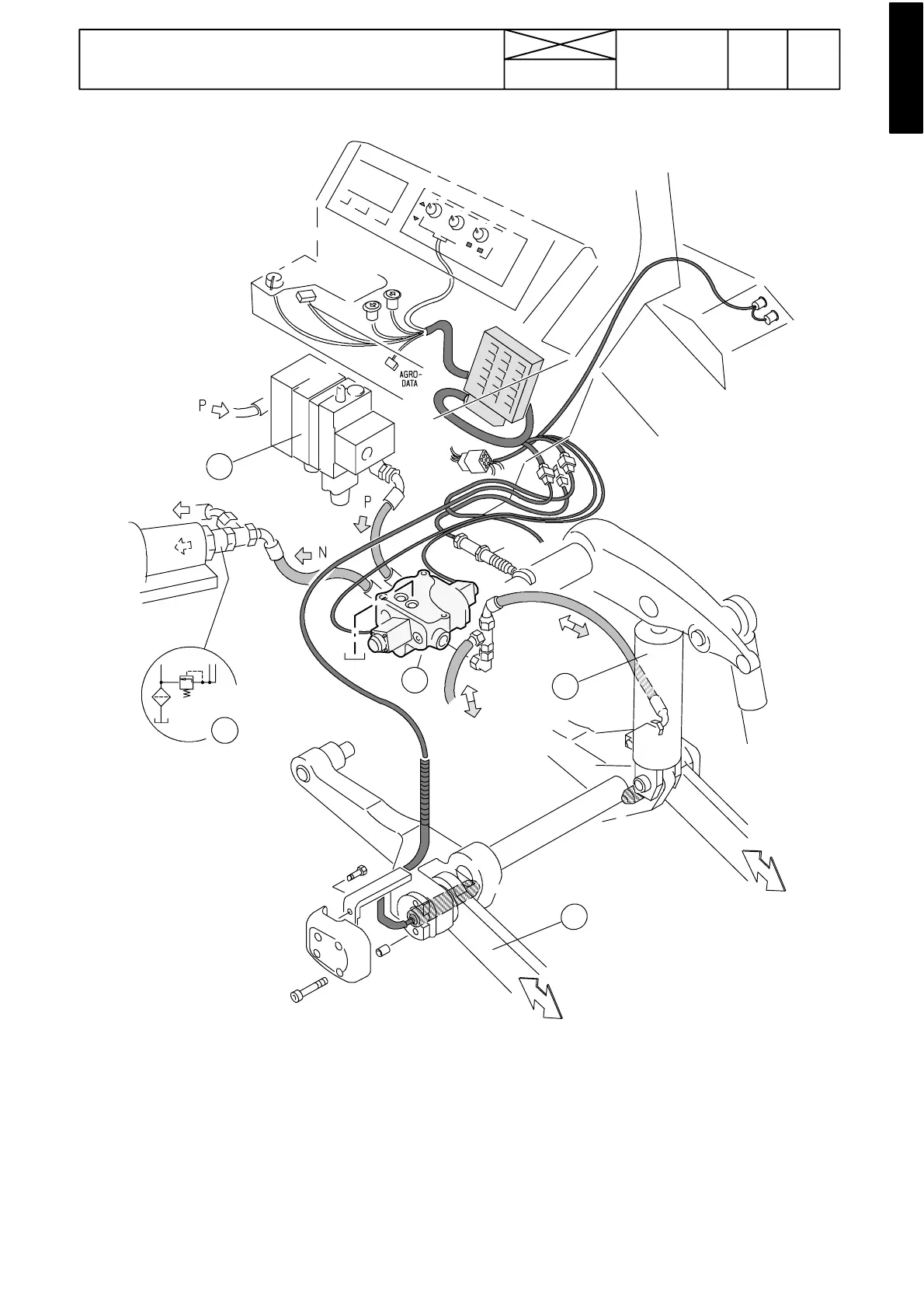
Figure 7. Hydraulic lift
1. Control valve (Bosch EHR ---4)
2. Lifting cylinders (2 pcs)
3. Valves for auxiliary hydraulics
4. Pressure---limiting valve (lubri-
cating system)
5. Lower links
1223
Model Code Page
90. Hydraulic system
8. 11. 1990
6000--8750 910 13
Hydraulic power lift
1
4
2
3
5
A
The hydraulic lift control valve (1) is fitted on the RH side of the
gearbox. Oil flows to the control valve from the high pressure
pump via the priority valve and via the valves for the auxiliary
hydraulics (3) (hose P).
Electrically controlled valve (1) directs oil to the lifting cylin-
ders (port A) in the lifting position. In the lowering position, the
oil returns to the oil reservoir (gearbox housing). In the neutral
position, the valve holds pressure in the lifting cylinders and
the valve is in the free---circulation positio n (hose N).
The free---circulating oil (below 0,2 MPa) flows to the trans-
mission lubricating system.
Thecontrolvalve(1)hasanin---builtshockvalve(20MPa)
which protectthe working hydraulics against pressureshocks
from the lifting cylinders.
W o rking hydraulic pressure is limited by a pressure---limiting
valve (19 MPa) which is placed on the underside of the end
plate (inlet side) of the auxiliary hydraulic valve block (3) .
Electrical system of the hydraulic power lift is described in
section 32 (Electro---hydraulic power lift).