1251
Model Code Page
90. Hydraulic system
8. 11. 1990
6000--8750 912 5
Three---point linkage and towing
hook
1
2
3
Lower links
If the lower link (1) must be changed, first remove the draft
senso r cover (2) and the draft sensor locking piece (3). Now
the lower link can be removed after the draft sensor is pulled
out.
Pick--up hitch
When removing the pick---up hitch the lowerlinks must be de-
tached first. After that drive out the locking pins of the pick---
up hitch shaft and remove the pick---up hitch shaft.
Note! Remove the check link bracket from one rear axle hous-
ing. Remove, if necessary one rear wheel, if the pick---up hitch
shaft cannot be pulled out from its place.
The pick---up hitch loosens when the locking pins at the front
end of the hitch is removed. Now the hitch releases from its
cast iron guide ways under the gearbox housing.
Lifting arm shaft
If the lifting arm shaft has to be changed, the PTO housing
must be detached from the tracto r. Then remove the PTO unit
front cover and the PTO clutch shaft.
Remove the position sensor cam from the lifting arm shaft
through the opening in the upper part of the PTO housing.
Remove the lifting arms and pull out the lifting arm shaft from
its lo c ation on the PTO housing.
Note! Do not damage the position sensor when removing the
PTO housing. Remove the position sensor always before de-
taching the PTO housing from the tractor (see section 46).
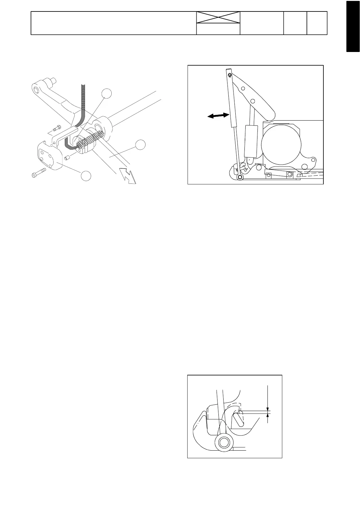
Adjusting pick---up hitch lifting links
6181---125
The lifting links should always have a certain amount of clear-
ance when the hydraulic lift is in its upper position. However,
they must be adjusted in such a way that the pick---up hitch
is securely locked by the pawl, even when the towing hook
is loaded.
Before adjusting, raise the hydraulic lift to its upper position
using the position control knob (towing hook unloaded).
Check the adjustment by moving the lifting links manually.
Adjustment is correct when the link moves loosely and when
the lift is lowered the towing hook is locked positively by the
pawl. Make sure that the spring returns the pawl fully home.
Adjust the length of the links if necessary by removing the
cotter at the upper end of the linksand turning until the correct
length is obtained. Check that both lifting links are the same
leng th after adjustment.The lifting links may be tightened
when lifting with push buttons.
Correctly adjusted lifting links ensure that the hydraulic lift can
be raised to its uppermost position. The pick---up hitch is
locked when the lift is lowered to the point where the hitch
restsonthe pawl, thereby preventing unnecessa ry loading on
the hydraulic pump and overheating of the oil.
Checking locking of pick- -up hitch
6--8 mm
6181---126
Make sure that the spring returns the pawl fully home. When
thepawl is turnedupwards the pick---up hitch should moveup
by 6 --- 8 m m .