279
Model Code Page
31. Autocontrol 2.2 / 2.3
1. 8. 2000
6000--8750 314 7
1. 6. 1999
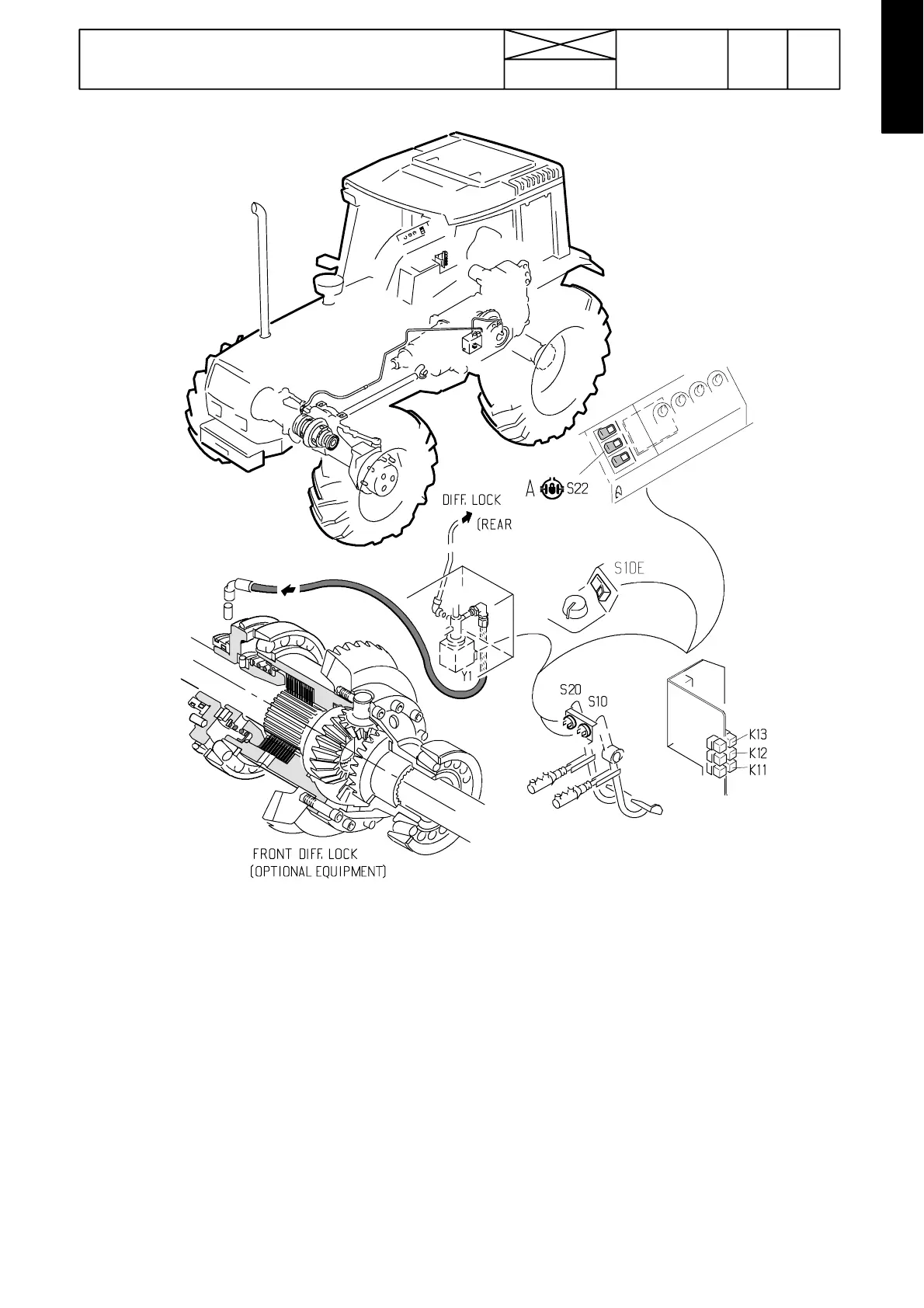
E. Differential lock control
Picture 3. Differential lock component
Y1: Diff. lock solenoid
K11, K12 (not in AC 2.3) and K13: control relays
S10 and S20: brake light switches
The differential lock rocker switch S22 is placed on the
sel ector panel on the driver’s righ t. In addition, the lift/stop/
lower switch of the ACB power lift also controls the diff.
lock.
The relays are placed in the lever console and are access-
ible after removing the console side panel:
K11: Switches off voltage to the diff. lock solenoid valve
and switches on current to the brake lights, when the
brake pedal/pedals are depressed. Switches on volt-
age again to the solenoid valve, when the brake
pedal/pedals are released. Ind. light comes on.
K12: Switches on voltage to the solenoid valve, when the
rocker switch rear edge is depressed. Ind. light
comes on. When the brake pedals after this are
depressed, relay K11 is closed and current from relay
K12 is cut---off and the relay opens and switches off
current to the solenoid valve and the ind. lights goes
out. The diff. lock does not engage after this although
the brake pedals are released. Note! This relay is not
fitted in AC 2.3.
K13: Switches off voltage to the solenoid valve and the lock
disengages, when the lift/lower switch is in the lifting
position. The lock ind. light , however, illuminates.
When the implement is lowered down to the working
position, switches on voltage to the solenoid valve
and the differential lock is engaged.