301
Model Code Page
32. Electro---hydraulic power lift
1. 8. 1998
6000--8400 320 15
15. 5. 1996
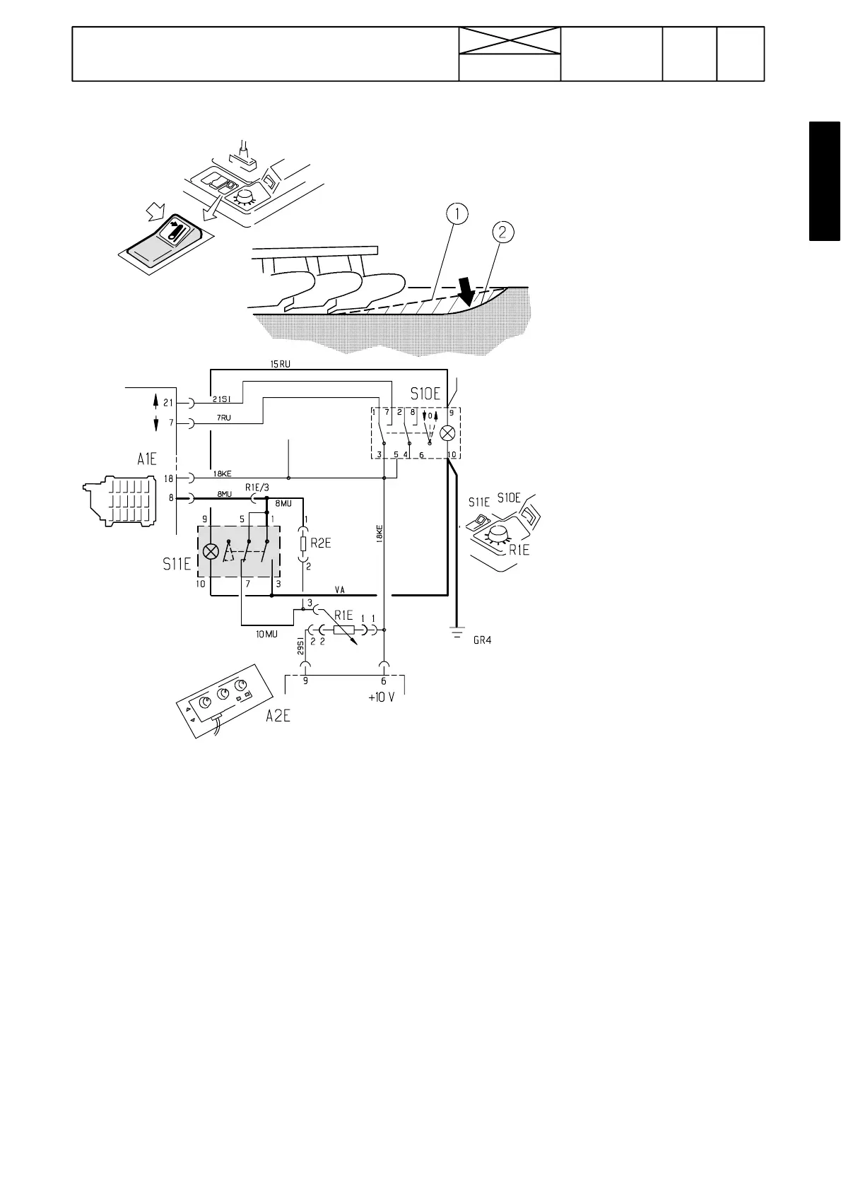
Forced ---lowering switch, 668103---.
Picture 2. F orced ---lowering switch
1. Without switc h
2. With switch
S11E=forced lowering switch
S10E=lift/lower switch
A1E=control unit
A2E=switch panel
R1E=position control potentiometer
The forced lowering switch is placed
ontheRHsideofthepositioncontrol
knob. When the switch rear edge
(spring returned) is depressed, the
Autocontrol adjustements are overid-
den (position control knob, sensitivity/
mixing), and lower links lower to the
lowest position (control unit pin 8
becomes earthed).
The lower links lowers so long the
switch is depressed. When the switch
is released, the lower links automati-
cally find the position determined by
position control knob.
The forced lowering switch does not
override the lowering speed setting.
The switch does not lower the lower
links, if the lift/lower switch is in the lif-
ting position or in the intermediate
position.
If the position control knob is in max
lowering position (max anticlockwise),
the switch does not lower the links any
more.
Note! F r o m s p r i n g --- 9 6 t h e f o r c e d ---
lowering switch is an option. On ACD
hydraulic lift (see under code 321) the
forced lowering switch is a standard
equipment.
Note! Resistance R2E has been added
in the electric circuit of the forced---
lowering switch.