431
Model Code Page
35. Autocontrol IV
1. 4. 1997
6600E
8100E-- 8750E
352 5
1. 1. 1994
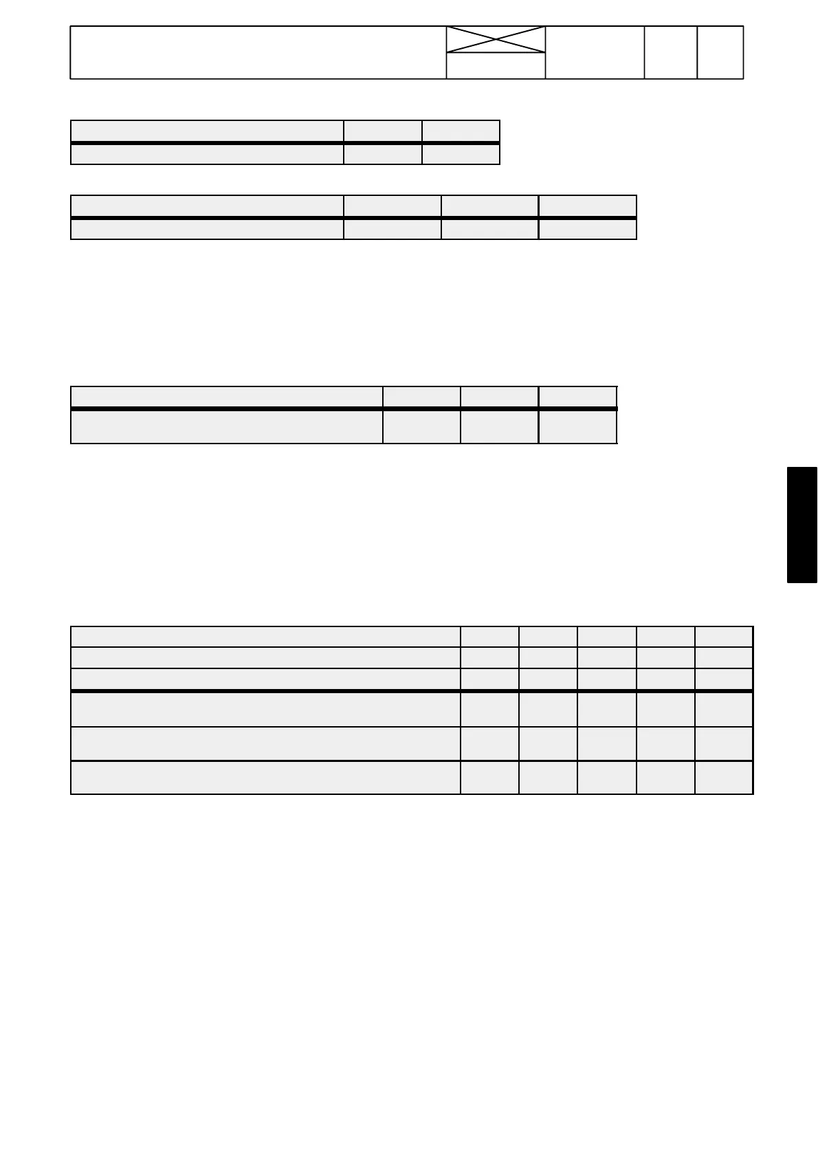
MAIN CLUTCH (A2C/18) 1 0
CLUTCH PEDAL (U=UP, D=DOWN) U D
STEERING ANGLE (A2C/15) 0 1 1
FRONT WHEELS STRAIGHT RIGHT. 15˚ LEFT 15˚
--- If the marks above the thick lines agree with the corresponding marks on the PC, the input signals are OK. If not, the fault lies
in the switch or sensor in question or their wirings are faulty.
--- Input signals from the radar, front axle sensor and rear axle sensor are checked with the calibrating drive, see page 351/2 or
see instruction F on page 352/7.
Output signals from ECS (DIGITAL OUTPUTS)
DL SOLENOID AND LAMP (A1C/37) 0 1 0
A / M --- S W I T C H (M
1=
rear edge down, M
2
=middle pos.,
A=front edge down.
M
1
M
2
A
--- If the marks above agree with the corresponding marks on the computer display, but there is malfunctions, the possible fault
lies in the solenoid valve or ind. light or their wiring is incorrect.
--- If the output signals lack, the ECS is faulty and should be replaced.
D. Power take---off control (---F17106)
Note! From tractor ser. no. F17107 incl. the PTO system has a relay control, see AC II under code 311.
Input signals to ECS (DIGITAL INPUTS)
PTO 540 1/0 (A2C/11) 0 1 1 0 0
PTO 1000 1/0 (A2C/12) 0 0 0 1 1
PTO 1/0 (A2C/13) 0 0 1 0 1
PTO 540 ON/OFF (ON=lever in front position, OFF=lever in middle
position)
OFF ON ON OFF OFF
PTO 1000 ON/OFF (ON=lever in rear position, OFF=lever in middle
position)
OFF OFF OFF ON ON
PTO ON/OFF (ON=lever knob switch in front position, OFF=rear
position)
OFF OFF ON OFF ON
--- If the marks above the thick line agree with the corresponding marks on the computer display, the input signals are OK. If not,
the fault lies in the switch in question or its wiring is incorrect.
--- The engine speed sensor and the PTO speed sensor are checked according to the instructions on page 351/3 or according
to instruction F on page 352/7.