161
Model Code Page
37. Autocontrol 5.2 (K41107---)
1. 9. 2002
371 9
6250--8950
1. 8. 2000
C. Table to check the temperature sensors and position sensors (A1---A8) in the test mode
in AC 5.2
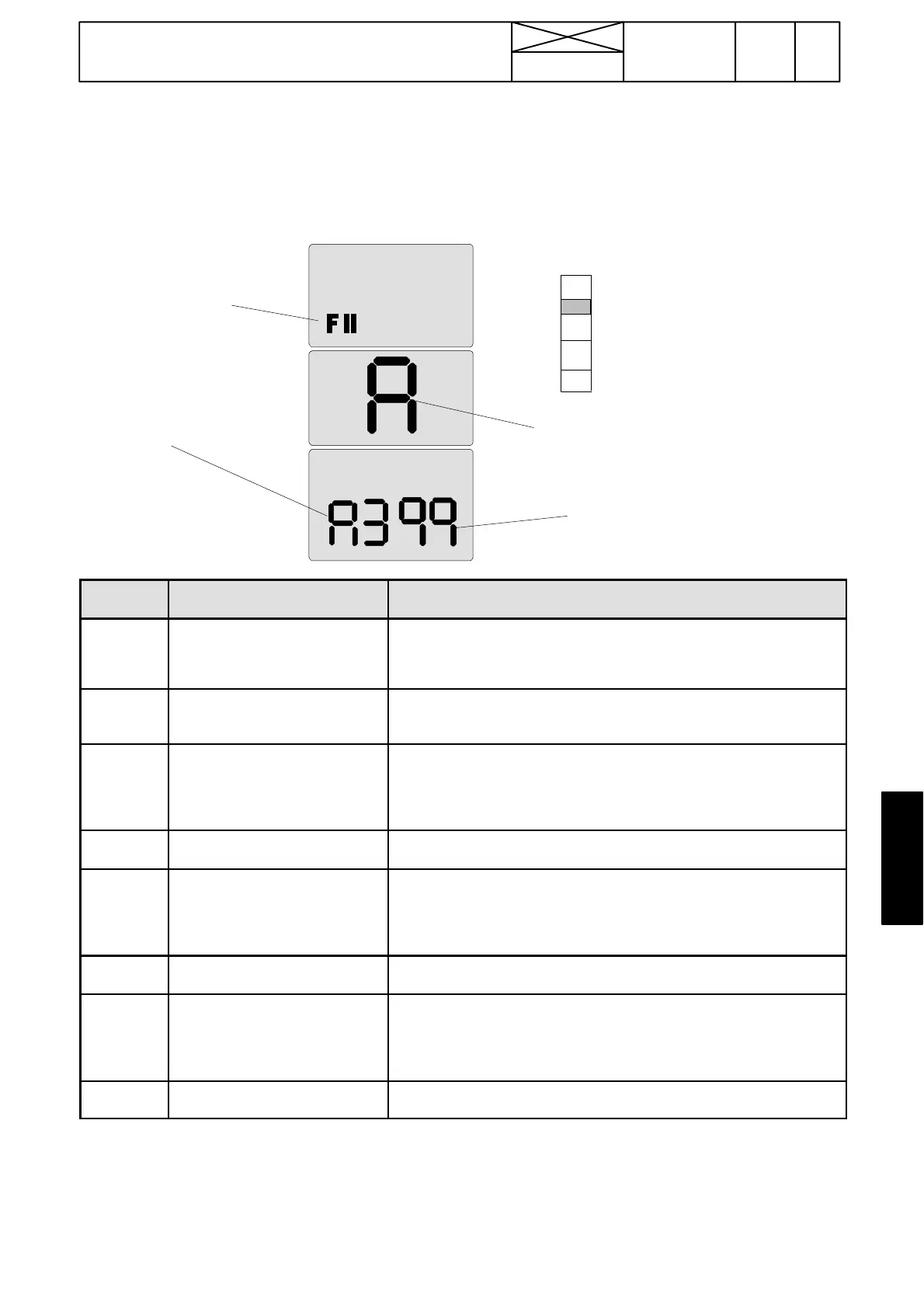
Activate the test mode FII (see page 370/8) and select with the DPS push buttons a wanted test point and confirm the selectio n
with the DPS pre ---programming button, after which the required point can be checked. When the test has been done, press again
the DPS pre ---programming button, after which can be selected an other test point with DPS push buttons etc.
Example:
99=gas pedal in bottom
(the value must be smaller
than 2 when the pedal is
up).
Module symbol A=AC 5.2
A3=gas pedal
FII=test
mode
symbol
F
A
d
P
C
DIGITAL
INPUT
NAME DESCRIPTION
A1 (B17)
Outdoor temperature (xx ˚Cor
xx˚F)
Compare the value with the ambient outdoor temperature. If the values
are different or not visible, check the sensor wires and sensor itself, see
instr A on page 371/13. If the temperature is below ---9˚ C, the display
shows “LO”.
A2 (B14) Gearbox oil temperature ( xx ˚C) Compare the re ading with the ac tual gearbox temperatur e. If the values
are different or not visible, c heck the wires and the sensor, see instr. A on
page 371/13. If the temperature is below ---9˚ C, the display shows “LO”.
A3 (B15) 1) Gas pedal position (xx %) *) When the pedal is fully up, the value shoul d be smaller than 2. When the
pedal is in bottom, the value should be greater than 99. Check also that
the value changes evenly when the pedal is moved (in the middle of the
pedal stroke, the value should be about 50). If the values deviate from
corret values, see instr. D on page 371/14.
A4 (B15) 1)
Gas pedal pos. sensor signal,
Volts.
Gas pedal fully up, s ignal between 2,0...4,7 V. Pedal in bottom, si gnal
between 0,3...3,0 V.
A5 (B16) Front clutch pedal position (xx %)
*)
When the pedal is fully up, the value should be greater than 97.Withthe
pedal at the bottom, the value should be smaller than 2.Alsocheck,that
the value changes evenly when the pedal is moved (in the middle of the
pedal travel, the value should be about 50). If the values deviate from the
above given values, see instr. B on page 371/13.
A6 (B16)
Front clutch pedal pos. sensor
signal, Volts.
Clutch pedal in bottom, signal between 2,5---4,7 V. Front clutch pedal
fully up, signal between 0,3---2,4 V.
A7 (B1W) Rear clutch pedal position (xx %)
*)
When the pedal is fully up, the value should be greater than 97.Withthe
pedal at the bottom, the value should be smaller than 2.Alsocheck,that
the value changes evenly when the pedal is moved (in the middle of the
pedal travel, the value should be about 50). If the values deviate from the
above given values, see instr. B on page 371/13.
A8 (B1W)
Rear clutch pedal pos. sensor
signal, Volts.
Clutch pedal in bottom, signal between 2,5---4,7 V. Rear clutch pedal
fully up, signal between 0,3---2,4 V.
Note! Compare signals from the temperature sensors and position sensors with values in the table above. If the signal from one
sensor is not co rrect, carry out the required repairs, see e.g. pages 371/13 and 14.
1) The gas pedal of reverse drive controls (TwinTrac, option) affect the same sensor as the front pedal. If the rear pedal signal
value is not within given limits, the rear pedal wire must be adjusted so that the fuel injection adjusting lever moves the hole stroke.
*) The pedal position sensor must be calibrated before checking %---values.