648
Model Code Page
41. Clutch
6000--8750 410 12
1. 4. 1997
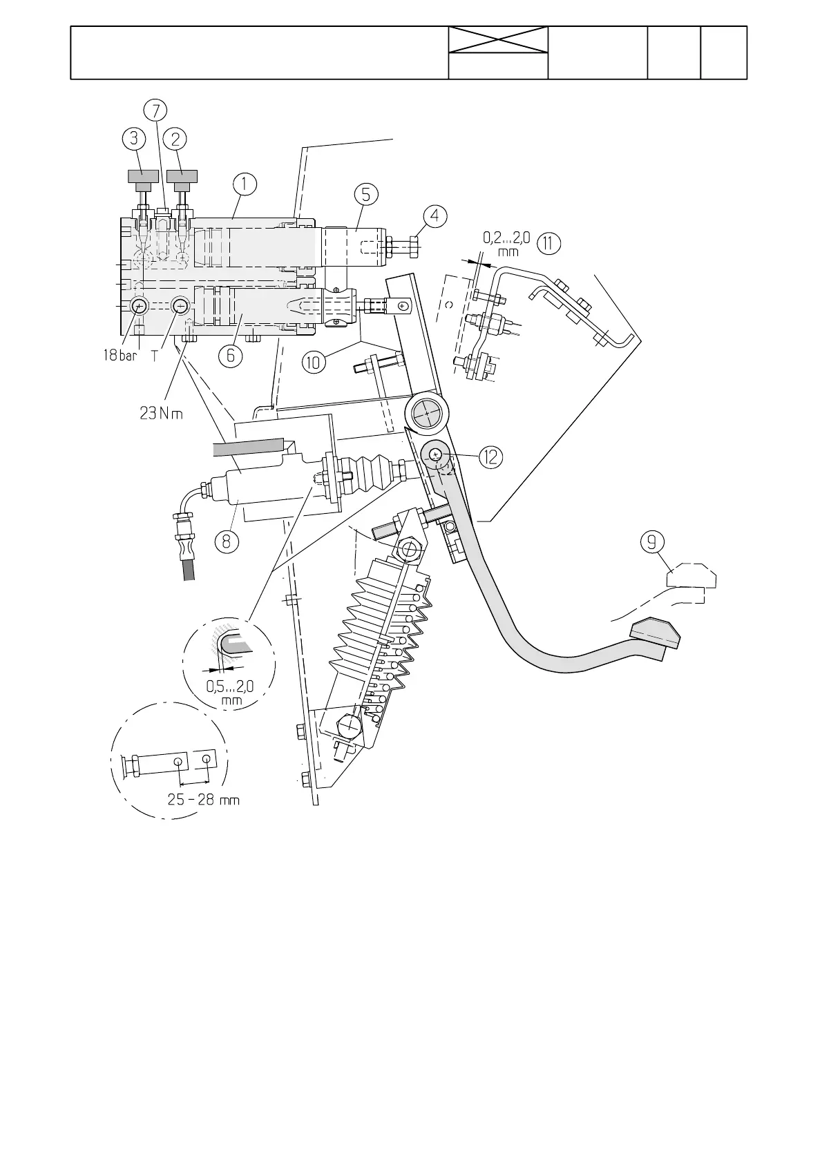
Picture 10. HiShift hydraulic block and clutch pedal
1. HiShift hydraulic block
2. Adjustable restriction for clutch pedal rising speed
3. Adjustable restriction for clutch pedal rising speed
4. Adjusting screw for adjusting position of knee point
(knee point is a point, where clutch starts to slip and
engage when it rises from lowest position upwards)
5. Damping piston
6. Main hydraulic piston
7. Damping cylinder filling valve
8. Clutch master cylinder
9. Clutch pedal
10. In the upper position the pedal should rest against the
stop and working cylinder piston (6) push rod must be free.
Push rod clearance to the piston hole edges should be at
least 1 mm in the whole pedal travel.
11. When piston ( 6) is fully pushed out, clearance to the
stopper should be 0 , 2 --- 2 m m .
12. All sliding and bearing surfaces should be greased with
universal grease in connection with repair works.
Others
Normal foot control of the pedal is always possible, also
simultaneously. The clutch pedal has a hinge for safety.
The clutch master cylinder and the clutch release mechan-
ismarethesameasearlier.
Note! HiShift can be retrofitted also on earlier manufac-
tured tractors, although they do not have the Agrodata---
instrument.
HiShift hydraulic block fixing bolts are tightened to 23 Nm.
Theboltsmustnotbetightenedtoohard.