662
Model Code Page
41. Clutch
6000--8750 411 14
1. 4. 1997
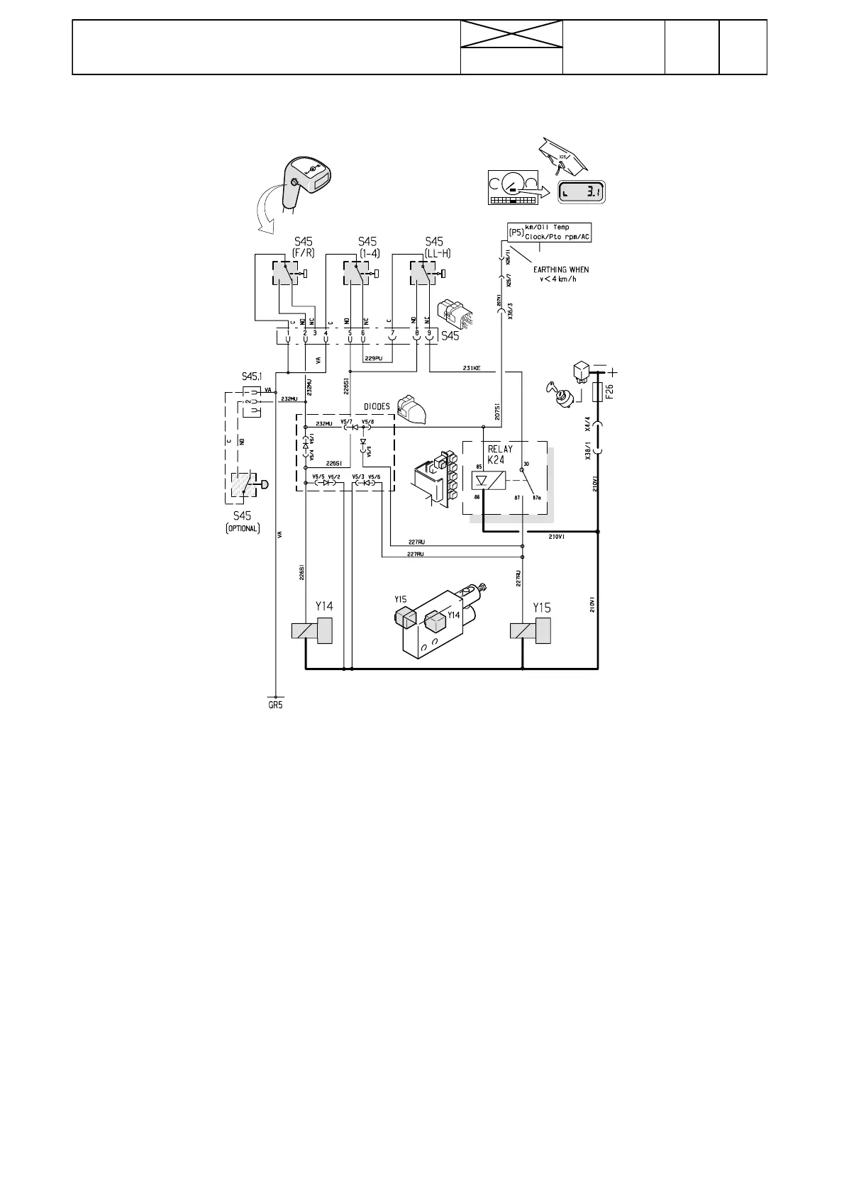
C. HiShift electric system
Note! When the but tons are pushed, the solenoid valve
Y14 is grounded and it becomes energised and the clutch
pedal is depressed. AD---instrument grounds via relay K24
the sol eno id valve Y15, when driving speed is under 4
km/h, and the pedal rises up slower. When the shuttle lever
buttonisused,thevalveY15isalwaysgroundedregard-
less of the driving speed.
---If the HiShift does not function:
--- check fuse F26. If the fuse blows repeatedly, the fault
can lie in diodes.
--- check the resistance of the solenoid valves which should
be 11---12 ohms.
--- when 12 V is fed to the valve pins, the valves must
become magnetic and the spindle must move (click).
IfthefuseandthesolenoidvalvesareOK,buttheHiShift
has malfunctions:
---measurewhetherthereisavoltageof12V inthecon-
nector pins of Y14 when the buttons are depresse d. If not,
the fault can lie in the valve wires or in the push buttons.
Check/ /correct.
If the pedal rising speed has malfunctions:
---measurewhetherthereisavoltageof12Vinthecon-
nector pins of valve Y1 5 when the driving speed is under 4
km/h or the tractor is stationary. If not, the fault lies in relay
K24 or in valve wires.
--- when driving speed is over 4 km/h, the valve Y15 should
be unenergised and the pedal rises up faster.
--- If the pedal rises never slower when using all three but-
tons, the relay K24 is faulty.
If the pedal does not always rise slower when using the
shuttle lever button
--- check function of other buttons. If with the other buttons
the Hi Shift functi ons correct, but not with the reverse
shuttle lever button, the fault lies in the diodes.
Valve Y15 has been connec t ed to the speed sensor B6 of
the AD---instrument. If the instrument shows correct speed
and travelli ng distance, the sensor B6 is in order. Otherwise
the sensor should be checked/changed, see page 331/4.
Diode housing V5 is placed in the steering wheel co nso l e.
In case of diode damages the whole housing should be
changed.
Earthing point GR5 is under the dash boar d (cab wire
loom).
Relay K24 is situated in the lever console beside the relays
for the AC II.
Note! The push button wires have been soldered to the
buttons. As a spare part is dispatched wires together with
the buttons. The wire lower ends have connectors